
Spring retainer and method for manufacturing the same

a spring retainer and spring technology, applied in the direction of engines, mechanical equipment, machines/engines, etc., can solve the problems of increasing the cost of the valve spring retainer for the engine, increasing production costs, etc., and achieve the effect of high uniform outer diameter

Inactive Publication Date: 2007-06-12
HONDA MOTOR CO LTD +1
View PDF4 Cites 0 Cited by
  • Summary
  • Abstract
  • Description
  • Claims
  • Application Information

AI Technical Summary

Benefits of technology

The present invention provides a spring retainer for valve springs that can be made using a titanium alloy and cold forging techniques. The brim of the retainer is compressed obliquely downward during cold forging, resulting in a decreased thickness of the brim in a radially outward direction. This helps to suppress shrinkage and anisotropy of the outer diameter, making it possible to mass-produce the retainers. The titanium alloy used in the invention contains iron, oxygen, and nitrogen, and the method for manufacturing the retainer involves at least five stages: cutting the titanium blank, upsetting the blank, punching a hole, cold forging it into a preform, and then cold forging it to obtain the final product. The use of cold forging allows for a more uniform material flow and results in a spring retainer with high uniformity of outer diameter.

Problems solved by technology

However, the Ti-6Al-4V-based α / β Ti-alloy has the problem that since it must be formed by hot forging, finishing is necessary to improve dimension accuracy or obtain a smooth surface, which increases production cost due to increase in number of steps and the like.
However, the β-type Ti alloy has the problem that the material is expensive, and that the life of the metal mold is short because of high deformation resistance in forging, resulting in increase in cost of the valve spring retainer for engine.

Method used


Image

  • Spring retainer and method for manufacturing the same
  • Spring retainer and method for manufacturing the same
  • Spring retainer and method for manufacturing the same

Examples


Embodiment Construction

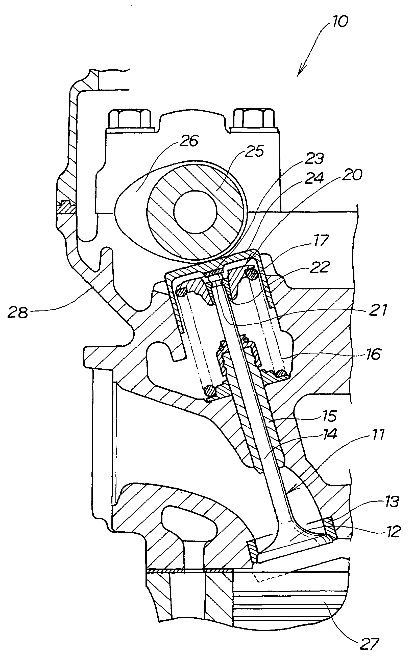
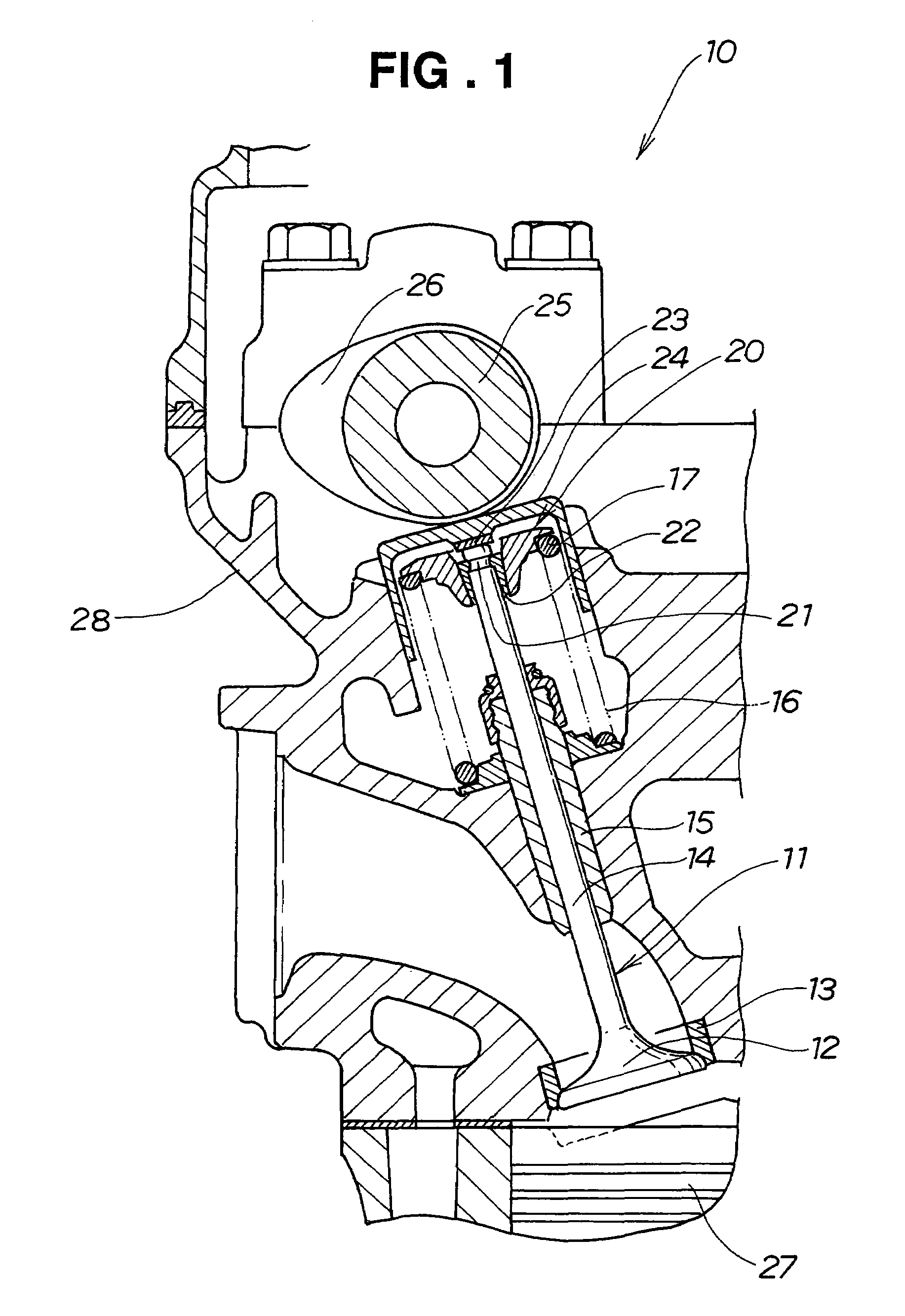
[0033]A valve operating mechanism 10 shown in FIG. 1 comprises a valve seat 13 for receiving a valve head 12 of an intake valve (or exhaust valve) 11; a valve stem 14 extending upward from the valve head 12; a valve guide 15 for guiding the valve stem 14; a valve spring 16 for biasing the intake valve 11 to the closed position; a spring retainer 20 for retaining one end 17 of the valve spring 16; a cotter 22 that is located inside the spring retainer 20 and fits in an upper recess 21 of the valve stem 14; an inner shim 23 provided at the upper end of the valve stem 14; a lifter 24 that covers the valve stem 14, valve spring 16, spring retainer 20, cotter 22 and inner shim 23; and a cam shaft 25 having a cam 26 which contacts with the lifter 24.

[0034]Reference numeral 27 indicates a piston, and 28 indicates a cylinder head.

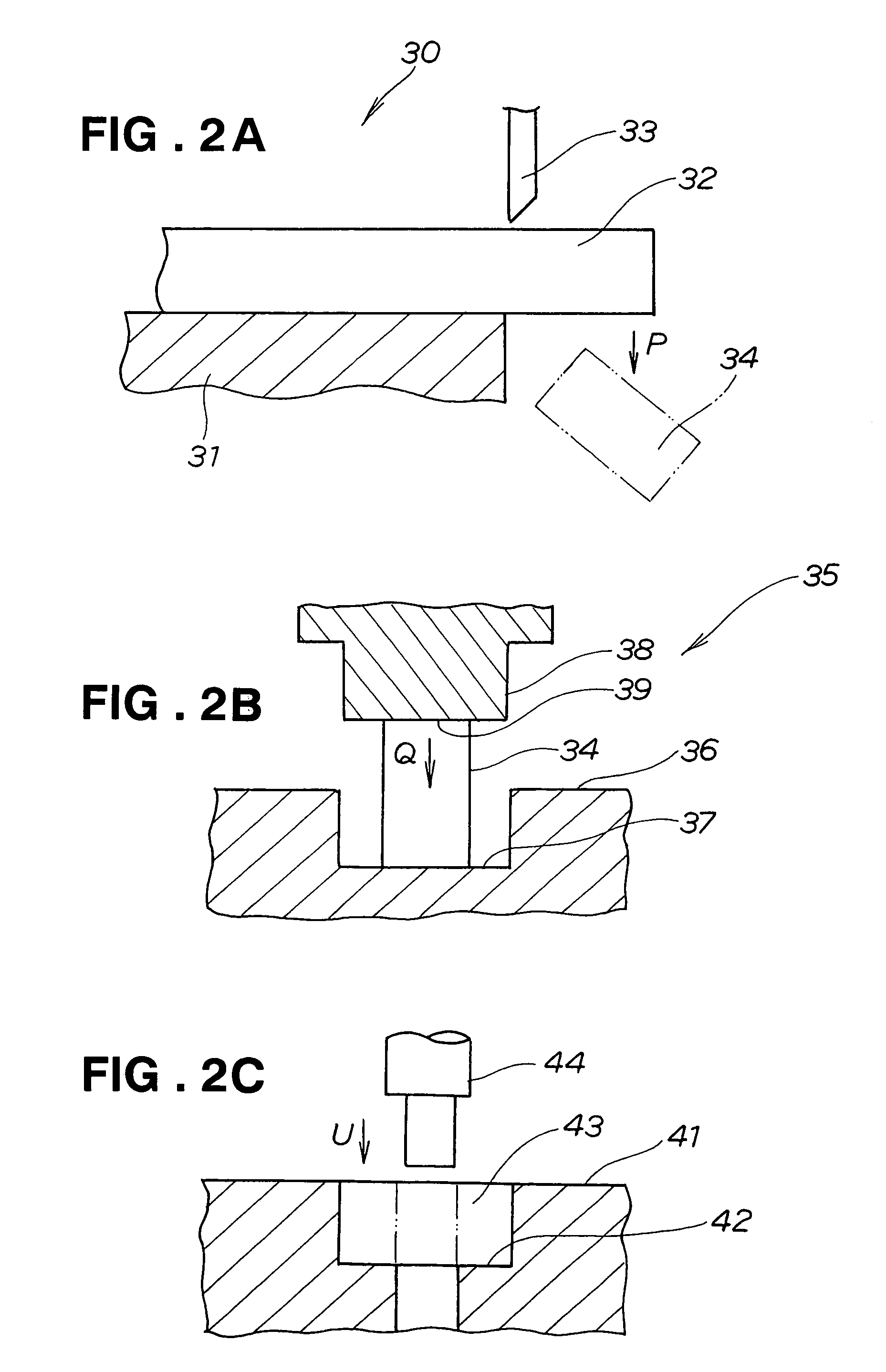
[0035]Steps from cutting of a titanium rod to cold punching are described according to FIG. 2A, FIG. 2B, and FIG. 2C.

[0036]First, as shown in FIG. 2A, a titanium r...


PUM

PropertyMeasurementUnit
outer diameteraaaaaaaaaa

Abstract

A spring retainer formed from a titanium alloy and comprising a cylinder and a brim formed integrally with the cylinder is disclosed. The brim has on a top thereof a slope formed such that a thickness of the brim decreases radially outwardly.

Description

FIELD OF THE INVENTION[0001]The present invention relates to an improvement in a valve spring retainer for an engine and a method for manufacturing the retainer.BACKGROUND OF THE INVENTION[0002]A valve spring retainer for engine acts to receive an end of a valve spring, and retain intake / exhaust valves and a cotter fitted in the valves, which are located inside the retainer, so that the valve spring does not unfasten during operation of the valves.[0003]JP-A-7-180013, for example, proposes a valve spring retainer for engine using a Ti-6Al-4V-based Ti alloy as a material. The valve spring retainer is now described with reference to FIG. 11 hereof.[0004]As shown in FIG. 11, the valve spring retainer for engine 200 has a through-hole 201 through which valves aligned along an axis pass, and receiving parts 202, 203 for supporting the valve spring at a periphery of the through-hole.[0005]JP-A-7-180013 discloses a technique for hot-forming the Ti-6Al-4V-based Ti alloy at 300 to 800° C. in...

Claims


Application Information

Patent Timeline
Patent Type & Authority Patents(United States)
IPC IPC(8): F01L1/00B21K1/22
CPCC22F1/183F01L3/10Y10T29/49298F01L2103/00F01L2303/00
Inventor HORIMURA, HIROYUKIDOI, KOSUKEKANAZAWA, YOSHIKAZUSAWAI, MASAHIRO
Owner HONDA MOTOR CO LTD
Learn More