Method for controlling engine starts for a vehicle powertrain

a technology for internal combustion engines and powertrains, which is applied in the direction of motor/generator/converter stoppers, dynamo-electric converter control, instruments, etc., can solve the problems of reducing the initial response time of the engine, merely adjusting the crank throttle position based on power demand or commanded torque, and reducing the initial response time. , the effect of reducing the initial response tim

Active Publication Date: 2007-06-12
FORD GLOBAL TECH LLC
View PDF11 Cites 21 Cited by
  • Summary
  • Abstract
  • Description
  • Claims
  • Application Information

AI Technical Summary

Benefits of technology

[0014]The invention includes a method for reducing response time for a driver demand for engine torque. Provision may be made during advanced accelerator pedal engine starts for reducing the smoothness of the engine in favor of a faster initial response time. The invention provides an adder to a crank throttle position as a function of the engine power that will be requested after the engine start. The engine torque command is initialized after the engine start to a percentage of the desired engine torque rather than to a value that always begins at zero. The adder for the crank throttle position prevents the manifold pressure from being reduced to a very low value during and immediately following engine cranking. The initialization of the commanded engine torque at the start of an engine running mode will ensure that the commanded engine torque will result in a throttle position that is at least as large as a crank throttle position. This allows the throttle to open quickly after the engine starting mode is completed.
[0015]The adder value for the crank throttle position is a function of the desired engine power. This allows the engine to be cranked at a larger throttle position at higher power demands. A minimum throttle position is used on low power engine starts to ensure that the initial combustion results in smooth engine operation. The adder minimizes the decrease in the absolute manifold pressure during engine starts with an advanced accelerator pedal position.

Problems solved by technology

The re-establishment of manifold pressure delays the response time of the engine.
Merely adjusting the crank throttle position based on power demand or commanded torque would not be sufficient to improve response time since the commanded torque must be changed smoothly from an initial engine torque command to the desired, or targeted, engine torque command.
Further, the smooth increase of the commanded engine torque from the initial engine torque to the desired engine torque may be too slow.

Method used


Image

  • Method for controlling engine starts for a vehicle powertrain
  • Method for controlling engine starts for a vehicle powertrain
  • Method for controlling engine starts for a vehicle powertrain

Examples


Embodiment Construction

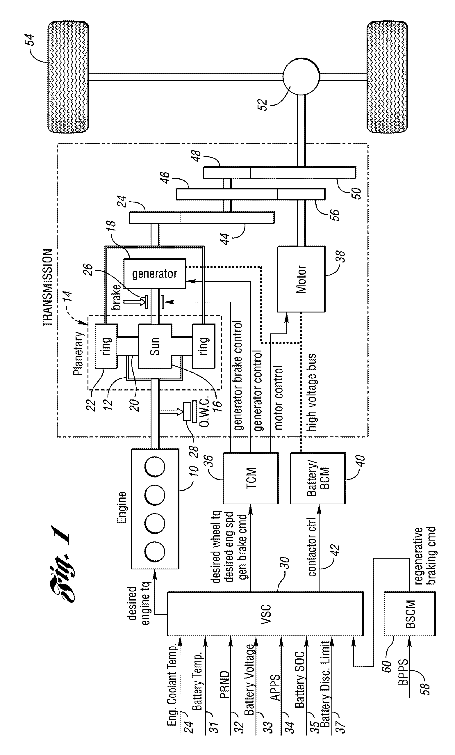
[0028]The invention may be applied to an internal combustion engine controller in powertrains other than powertrains for hybrid electric vehicles, but the embodiment disclosed herein includes a hybrid electric vehicle powertrain with an internal combustion engine and an electric motor coupled to transmission gearing.

[0029]In the hybrid powertrain configuration schematically illustrated in FIG. 1, a torque output crankshaft of internal combustion engine 10 is connected driveably to carrier 12 of planetary gear unit 14. Sun gear 16 of the gear unit 14, which acts as a reaction element, is driveably connected to generator 18. Carrier 12 rotatably supports planet pinions 20, which engage sun gear 16 and ring gear 22, the latter being connected driveably to transmission torque input gear 24. The generator 18 provides reaction torque when the engine delivers driving power to the transmission. The generator, which is part of a motor-generator-battery electrical subsystem, develops electric...


PUM


Abstract

A method is disclosed for controlling an internal combustion engine in a vehicle powertrain. A filtered driver demand for torque at vehicle traction wheels is used to determine an engine torque command. The engine torque command is initialized to a percentage of a target engine torque as a function of variables that may include a smoothness factor.

Description

BACKGROUND OF THE INVENTION[0001]1. Field of the Invention[0002]The invention comprises a control for an internal combustion engine in a vehicle powertrain wherein the response time for a driver demand for driving torque is reduced and engine start smoothness is improved.[0003]2. Background Art[0004]Hybrid electric vehicle powertrains of known design can be classified generally into three main categories commonly referred to as series hybrid powertrains, parallel hybrid powertrains and series-parallel hybrid powertrains. In each case, two power sources are available for powering a driven element connected driveably to vehicle traction wheels.[0005]A series-hybrid powertrain comprises a fueled engine prime mover, which powers an electric or a hydraulic power transmission connected to a drive motor. The motor can be driven by a battery or by an engine driven generator. A parallel hybrid electric vehicle powertrain establishes parallel power flow paths from the engine through power tra...

Claims


Application Information

Patent Timeline
Patent Type & Authority Patents(United States)
IPC IPC(8): B60K1/02F02P5/00G06F19/00G06G7/70H02P1/00
CPCF02D29/02Y10T477/23Y10T477/30
Inventor NIESSEN, PAULOKUBO, CAROLGARTNER, PAULMORRIS, DANIEL
Owner FORD GLOBAL TECH LLC
Why Eureka
Try Eureka