Automated radioisotope seed loader system for implant needles

Inactive Publication Date: 2007-06-12
THERAGENICS CORP
View PDF35 Cites 83 Cited by
  • Summary
  • Abstract
  • Description
  • Claims
  • Application Information

AI Technical Summary

Benefits of technology

[0018]The automated system of the present invention advantageously uses a replaceable cartridge to transport and dispense the radioisotope seeds in a manner much safer and more efficient than current conventional manual practices. The replaceable cartridge is provided with sufficient shielding to i

Problems solved by technology

First, there are differences in the types of radioisotope sources that do not favor use of a cartridge arrangement for low dose radioisotope procedures.
Because the number of radioisotope seeds varies from procedure to procedure depending upon the dose plan and because the cost of each low dose radioisotope seed is significant, it is not cost effective to order many more radioisotope seeds than will be used in a given procedure.
The existing drop-in cartridge and seed magazine systems described above take longer to perform the implant procedure than using conventional preloaded implant needles because the radioisotope seeds are implanted one-by-one, rather than being delivered simultaneously as a group from a preloaded needle.
While some needle stands are provided with a certain degree of shielding once the radioisotope seeds are loaded in the implant needles, there is very little shielding that protects the hands and fingers of the

Method used


Image

  • Automated radioisotope seed loader system for implant needles
  • Automated radioisotope seed loader system for implant needles
  • Automated radioisotope seed loader system for implant needles

Examples


Example

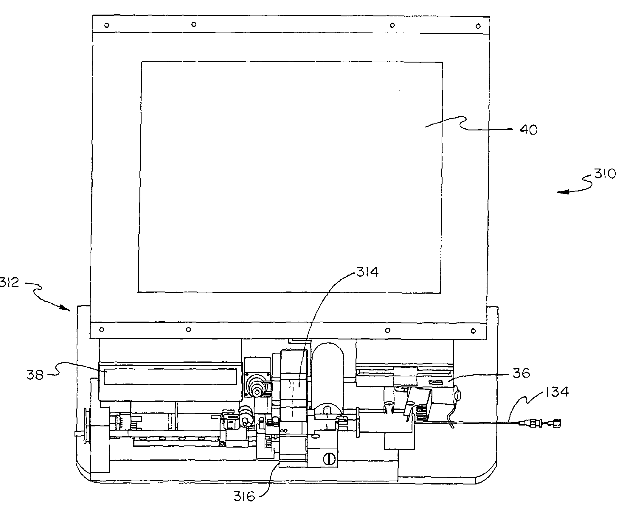
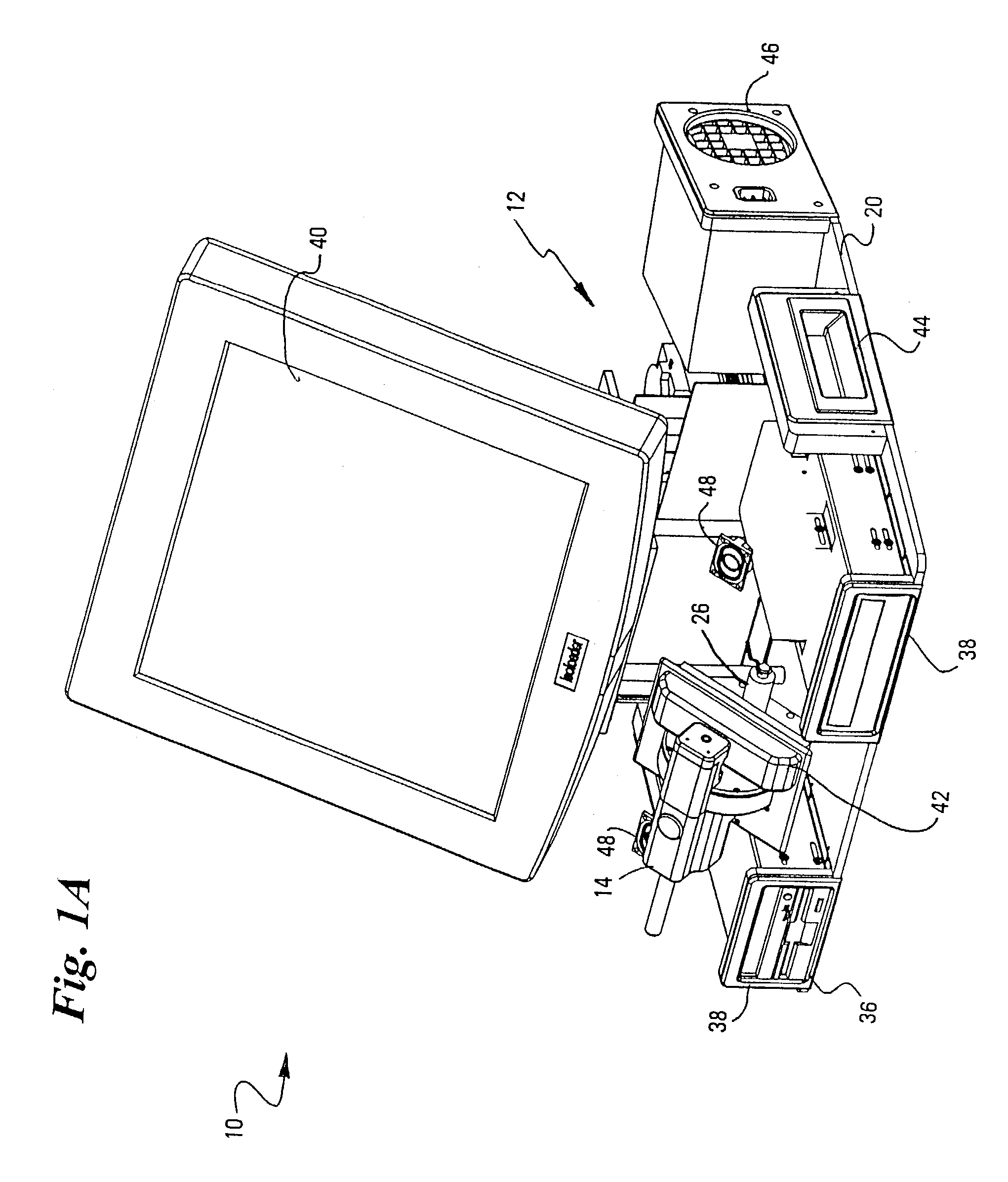
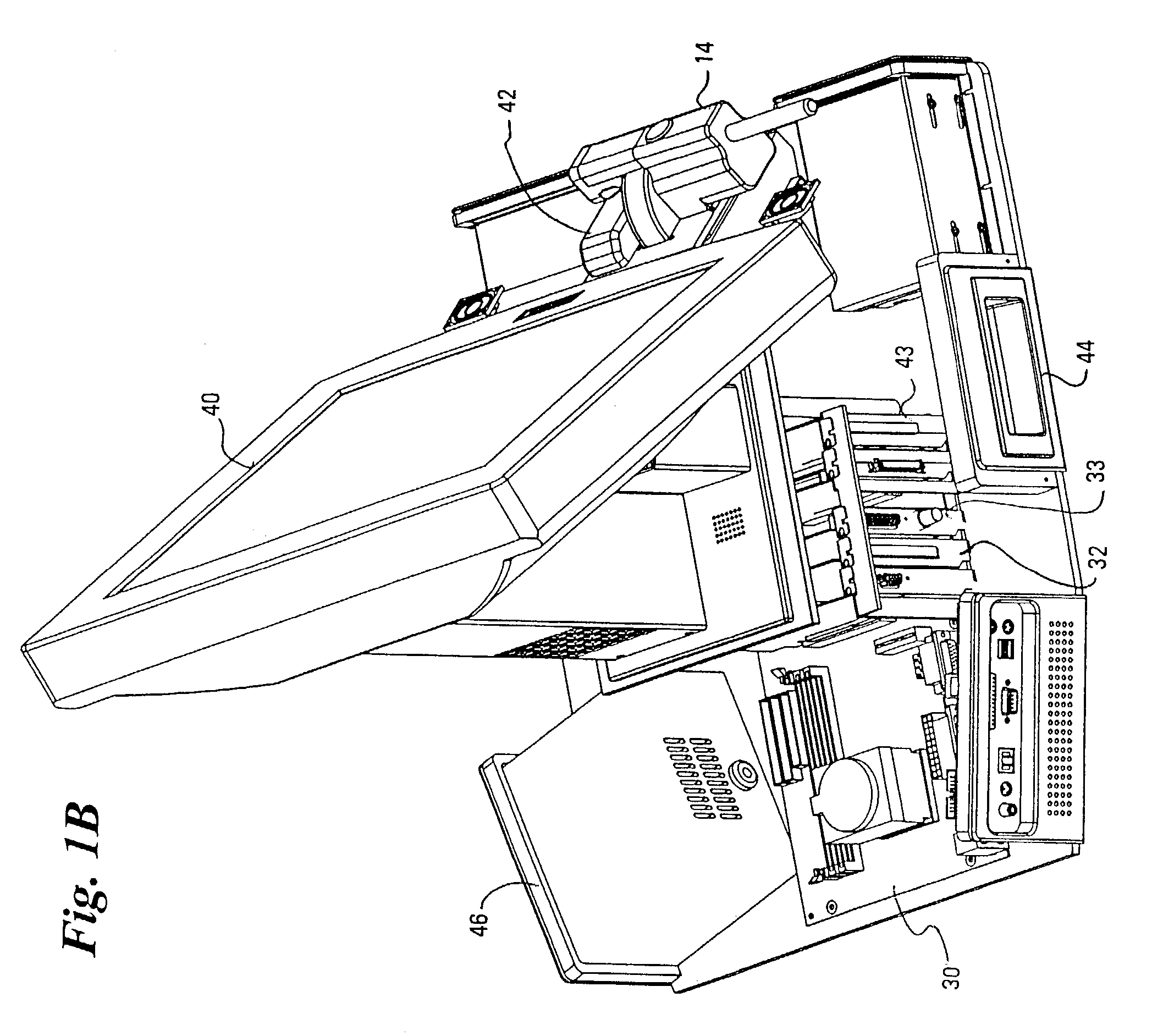
[0032]Referring to FIG. 1, an automated system 10 for loading low dose radioisotope seeds into a plurality of implant needles is comprised of a loading station 12 into which a replaceable cartridge 14 may be positioned. Preferably, the loading station 12 includes structure defining a cartridge receiving structure 16 in a front side of the loading station oriented toward a user as shown in FIG. 2. In this embodiment, the loading station 12 presents a front side toward a user with a corresponding longer dimension of the replaceable cartridge positioned in the cartridge receiving structure 16 parallel to this front side. Alternatively, the cartridge 14 and cartridge receiving structure 16 could be oriented transverse to the front side of loading station 12 or even at a rear side of loading station 12.

[0033]The loading station 12 has a base 20 (as shown in FIG. 1) and a cover 22 (as shown in FIG. 2) preferably formed of molded plastic or metal. A computer processor 30 for the automated ...


PUM


Abstract

An automated system for loading low dose radioisotope seeds into a plurality of implant needles is comprised of a loading station into which a replaceable cartridge may be positioned. The cartridge is preloaded with a plurality of radioisotope seeds and a plurality of spacers. The cartridge has at least one aperture and preferably the radioisotope seeds and spacers are loaded around the periphery of a rotatable drum within the cartridge. The loading station has a cartridge receiving structure and an automated motion control system. When the cartridge is positioned in the cartridge receiving structure, the automated motion control system preferably drives a pair of stepper motors within the cartridge, one for rotating the rotatable drum and one for sliding a pushrod to selectively eject radioisotope seeds and spacers from the cartridge into each of a plurality of implant needles positioned so as to receive the radioisotopes seeds and spacers within the implant needle. In one embodiment, the implant needles are positioned tip first into the loading station, and once a predetermined arrangement of radioisotope seeds and spacers are loaded into the implant needle, a plug is positioned in the tip of the implant needle. Preferably, the automated system includes a computer processor having a touch screen user interface that is connected to and directs the operation of the automated motion control system to load the plurality of implant needles in accordance with a predetermined dose plan.

Description

RELATED APPLICATIONS[0001]This application is a continuation of application Ser. No. 09 / 587,624, filed Jun. 5, 2000 now U.S. Pat. No. 6,537,192, entitled “AUTOMATED RADIOISOTOPE SEED LOADER SYSTEM FOR IMPLANT NEEDLES,” which is related to a pair of co-pending applications that are commonly assigned to the assignee of the present invention entitled “RADIOISOTOPE SEED CARTRIDGE,” Ser. No. 09 / 587,642 now U.S. Pat. No. 6,616,593 and “LOADING CLIP FOR RADIOACTIVE SEEDS,” Ser. No. 09 / 658,636, now U.S. Pat. No. 6,599,231 the disclosures of which are incorporated by reference.FIELD OF THE INVENTION[0002]The present invention relates generally to the field of medical devices for handling radioisotope materials. More specifically, the present invention relates to an automated system for loading low dose radioisotope seeds into implant needles for use in brachytherapy procedures or the like.BACKGROUND OF THE INVENTION[0003]The use of radioisotopes for various medical procedures such as brachyt...

Claims


Application Information

Patent Timeline
IPC IPC(8): A61N5/00A61M36/12A61N5/10
CPCA61M37/0069A61N5/1007A61N5/103A61N5/1027A61N2005/1008A61N2005/1009A61N2005/1011
Inventor ELLIOTT, DANIEL M.HOEDEMAN, GEORGE M.BERKEY, JOHN J.ELLIOTT, JONATHAN D.
Owner THERAGENICS CORP
Why Eureka
Try Eureka