Battery pack apparatus with heat supply and discharge

a battery pack and heat supply technology, applied in the field of battery back devices, can solve the problems of difficult to keep the rechargeable batteries at a predetermined temperature stably, affect the surrounding temperature, and rechargeable batteries, and achieve the effect of regulating the temperature of the whole battery pack at a predetermined temperature efficiently and uniformly, improving thermal efficiency, and reducing the number of rechargeable batteries

Inactive Publication Date: 2007-06-12
PANASONIC EV ENERGY CO LTD
View PDF6 Cites 52 Cited by
  • Summary
  • Abstract
  • Description
  • Claims
  • Application Information

AI Technical Summary

Benefits of technology

[0012]A battery pack apparatus of the present invention includes: a battery pack composed of a plurality of rechargeable batteries arranged in parallel, the rechargeable batteries having heat medium passages formed therebetween; a heat insulation cover formed from a heat insulation material for covering a substantially entire circumferential surface of the battery pack with a supply passage and a discharge passage provided between the heat insulation cover and the battery pack, the supply passage supplying a heat medium to the heat medium passages while the discharge passage discharging the heat medium from the heat medium passages; and a supply device for supplying the heat medium to the supply passage. By making the heat medium flow in the heat medium passages between the rechargeable batteries, heat exchange occurs on the substantially entire surface of each of the rechargeable batteries and therefore the temperature control is performed efficiently and uniformly. Moreover, since the battery pack, the heat medium passage, the supply passage, and the discharge passage are covered with the heat insulation cover, escape of heat to the outside is prevented and transfer of radiation heat from the outside and heat from the surrounding atmosphere is also prevented, thereby improving thermal efficiency. Also, it is possible to regulate the temperature of the whole battery pack at a predetermined temperature efficiently and uniformly without being affected by the surrounding condition. Consequently, the increase and variation of the temperature is prevented, thereby making the battery life longer.

Problems solved by technology

However, the rechargeable batteries are affected by radiation heat from sunlight and heat radiated from an automotive exhaust pipe and are also affected by the surrounding temperature greatly.
Thus, it is difficult to keep the rechargeable batteries at a predetermined temperature stably and uniformly.
Further, there is another problem in which heat efficiency is not good.
Although this configuration is hardly affected by heat from the outside, cooling capacity is low and uniform cooling cannot be achieved.
Thus, the temperature of the rechargeable battery increases particularly around the center of the battery pack, resulting in a decreased battery life.
However, if it is tried to achieve the cooling capacity that can cool all the rechargeable batteries effectively only by using the heat pipe, a number of heat pipes, and a large amount of heat collecting material are necessitated.
This reduces space efficiency and increases the cost.
Nevertheless, it is difficult to uniformly cool the respective parts of the rechargeable batteries.

Method used


Image

  • Battery pack apparatus with heat supply and discharge
  • Battery pack apparatus with heat supply and discharge
  • Battery pack apparatus with heat supply and discharge

Examples


first embodiment

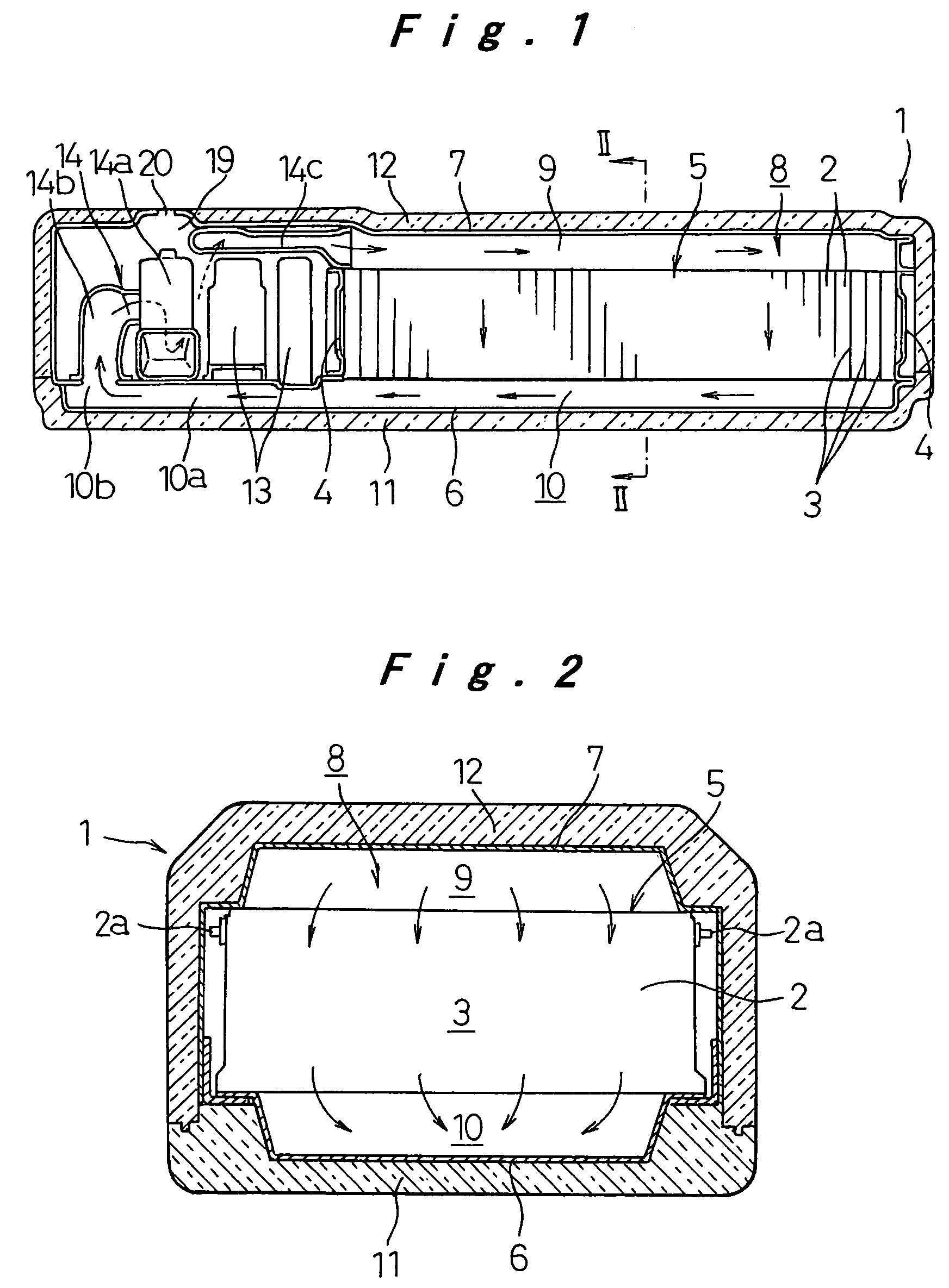
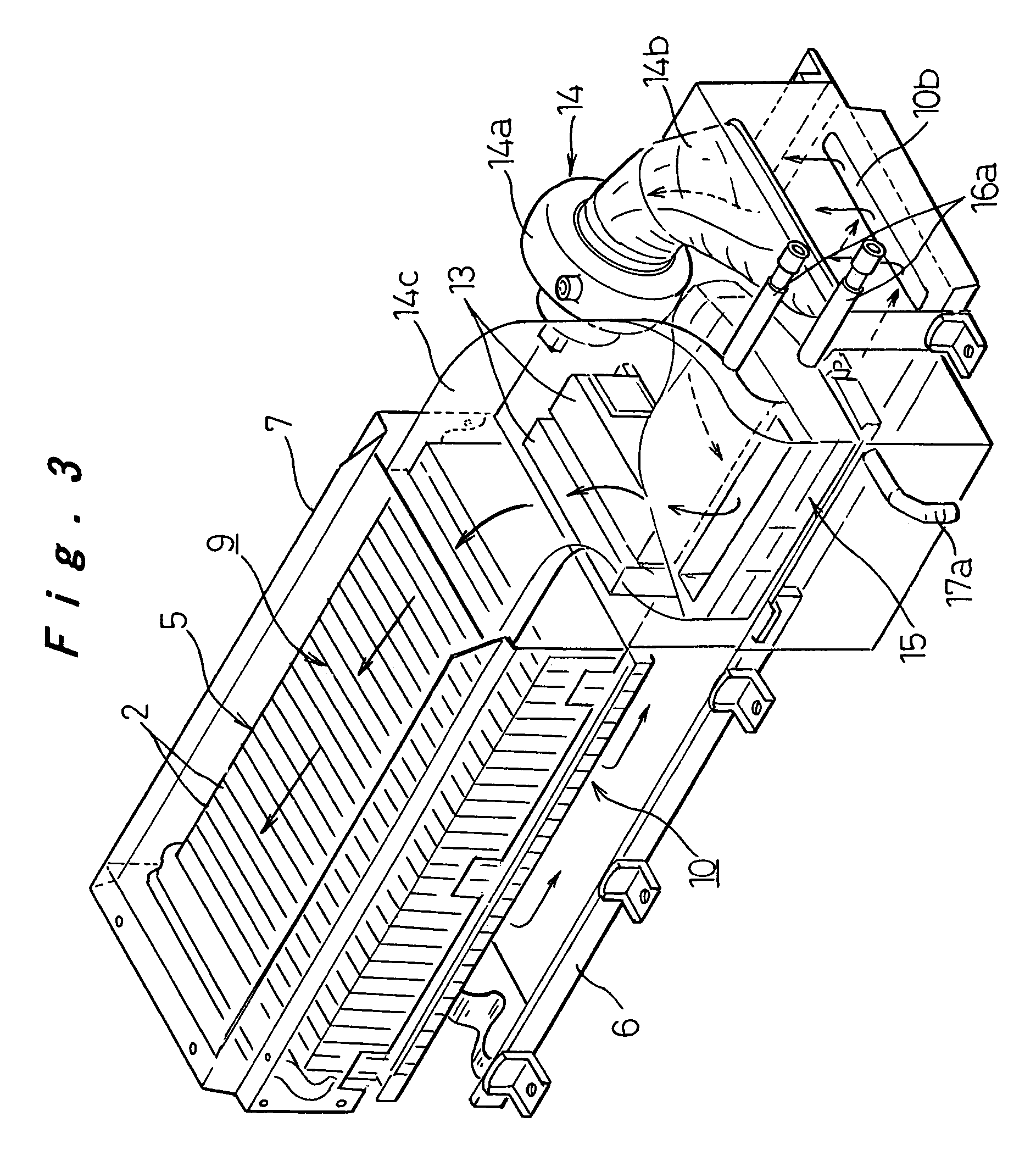
[0023]Hereinafter, a battery back apparatus according to a first embodiment of the present invention will be described with reference to FIGS. 1 to 6B.

[0024]Referring to FIGS. 1 to 4, a battery pack apparatus 1 serves as a drive power source for an electric vehicle including hybrid vehicles. The battery pack apparatus 1 contains a battery pack 5 composed of 10 to 30 flat prismatic rechargeable batteries 2 arranged in parallel with heat medium passages 3 provided between the long side faces of the rechargeable batteries 2. The rechargeable batteries 2 thus arranged are sandwiched by a pair of end plates 4 provided at both ends in the aligning direction, and are fixed as a unit by a binding member (not shown) to complete the battery pack 5. Each rechargeable battery 2 is a battery module in which a plurality of cells (not shown) are arranged in the longitudinal direction of the long side face of the rechargeable battery 2 and are electrically connected in series. At both ends of the r...

second embodiment

[0037]Next, a battery pack apparatus according to a second embodiment of the present invention will be described with reference to FIG. 7. In the following description of embodiments, the same components as those in the preceding embodiment are labeled with the same reference numerals, and the descriptions thereof are omitted and only differences are described.

[0038]In the first embodiment, the supply device 14 and the heating / cooling device 15 are accommodated in the accommodation space 8 covered with the heat insulation covers 11 and 12. On the other hand, in a battery pack apparatus 101 of the present embodiment, the battery pack 5 and the control unit 13 are accommodated in the accommodation space 8 formed by the lower case 6 and the upper case 7, while the supply device 14 and the heating / cooling device 15 are provided outside the accommodation space 8, as shown in FIG. 7. A supply space 9 is formed between the lower case 6 and the lower surface of the battery pack 5 while a di...

third embodiment

[0040]Next, a battery pack apparatus according to a third embodiment of the present invention will be described with reference to FIG. 8.

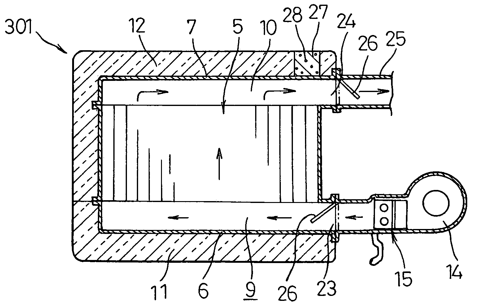
[0041]In a battery pack apparatus 201 of the present embodiment, the introduction port 23 and the discharge port 24 described in the second embodiment are formed in a side face of the accommodation space 8, that is parallel to the longitudinal direction of the battery pack 5. The introduction port 23 is provided in the upper region of that side face, while the discharge port 24 is provided in the lower region of that side face. Moreover, as is the case with the first embodiment, the supply passage 9 is provided above the battery pack 5 and the discharge passage 10 is provided below the battery pack 5, thereby making the heat medium flow downward into the heat medium passages 3.

[0042]The battery pack apparatus 201 of the embodiment is suitably applied to a case where the size of the battery pack apparatus in the longitudinal direction is limited.


PUM

PropertyMeasurementUnit
temperatureaaaaaaaaaa
charge/discharge efficiencyaaaaaaaaaa
heat efficiencyaaaaaaaaaa

Abstract

A battery pack apparatus includes a battery pack having multiple rechargeable batteries arranged in parallel and heat medium passages formed therebetween. The battery pack apparatus also includes a heat insulation cover formed of a heat insulation material that covers a circumferential surface of the battery pack substantially entirely. A supply passage and a discharge passage are provided between the heat insulation cover and the battery pack. The supply passage supplies a heat medium to the heat medium passages while the discharge passage discharges the heat medium from the heat medium passages. The battery pack apparatus also includes a supply device that supplies the heat medium to the supply passage.

Description

[0001]The present disclosure relates to subject matter contained in priority Japanese Patent Application No. 2003-80874, filed on Mar. 24, 2003, the contents of which is herein expressly incorporated by reference in its entirety.BACKGROUND OF THE INVENTION[0002]1. Field of the Invention[0003]The present invention relates to a battery back apparatus having a battery pack composed of a plurality of rechargeable batteries, in which the temperature of each of the rechargeable batteries is regulated stably and uniformly.[0004]2. Description of the Related Art[0005]In a battery pack composed of a plurality of rechargeable batteries, in order to prevent increase in the temperature of each rechargeable battery caused by heat generated by charge / discharge of the rechargeable battery and thus prevent decrease in a battery power, charge / discharge efficiency, and a battery life, it is conventionally known that the rechargeable batteries are arranged in parallel with cooling medium passages inte...

Claims


Application Information

Patent Timeline
Patent Type & Authority Patents(United States)
IPC IPC(8): H01M10/46B60K1/04H01M10/60H01M50/209H01M50/273H01M50/276H01M50/282H02J7/04
CPCH01M2/1077H01M10/5004H01M10/5008H01M10/5016H01M10/5087H01M10/5059H01M10/5067H01M10/5071H01M10/5073H01M10/5032H01M10/625H01M10/6563H01M10/647H01M10/6557H01M10/617H01M10/6565H01M10/6566H01M10/613H01M10/658Y02E60/10H01M50/273H01M50/209H01M50/282H01M50/276
Inventor KIMOTO, SHINYAKOBAYASHI, TAKAKI
Owner PANASONIC EV ENERGY CO LTD
Why Eureka
Try Eureka