Integrating electrometer amplifying circuit

a technology of amplifying circuit and electrometer, which is applied in the direction of radiation intensity measurement, instruments, material analysis, etc., can solve the problems of limiting the bandwidth of the measuring circuit, unable to generate discreet measurements, and unable to meet the needs of rapidly changing conditions, so as to prevent excess charging of the integrating capacitor, improve tracking of fluctuations, and limit the bandwidth of the integrating circuit output

Active Publication Date: 2007-06-12
MIRME AADU
View PDF12 Cites 12 Cited by
  • Summary
  • Abstract
  • Description
  • Claims
  • Application Information

AI Technical Summary

Benefits of technology

[0013]In a particularly preferred approach, the condition-monitoring voltage when in the operating range is higher than the first threshold voltage, lower than the second threshold voltage, and is reduced during integration of the incoming current. Then, the second circuit is configured to provide a stable low voltage to the feedback loop during integration. Upon sensing that the condition-monitoring voltage has been reduced to a level below the first threshold voltage, the circuit switches to apply a stable high voltage to the feedback loop to rapidly charge the integrating capacitor, thus driving the condition-monitoring voltage upward.
[0016]Yet another advantageous feature is a charge limiting circuit coupled between the second circuit and the feedback loop, to prevent excess charging of the integrating capacitor.
[0017]One favorable aspect of the present invention is that the amplifier or circuit gain is determined by the integrating capacitor, rather than by a high value feedback resistor. This removes a major source of circuit noise, essentially limiting circuit noise to that of the operational amplifier itself. With no need to limit the bandwidth of the integrating circuit output, the output is provided over a broader bandwidth for improved tracking of fluctuations in the aerosol particle suspension.
[0020]When integration reduces the integrating circuit output as in the preferred version discussed above, each capacitor reset cycle preferably includes a rapid charge, followed immediately by a rapid discharge. The discharge, terminated by entry of a descending condition-monitoring voltage into the operating range, positions that voltage near the upper limit of the range for another integrating cycle in which the condition-monitoring voltage is gradually reduced.
[0023]Thus, integrating electrometer circuits according to the present invention more accurately measure current fluctuations over a wide dynamic range.
[0026]Accordingly, aerosol particle measuring instruments constructed according to the present invention not only can produce finely divided aerosol particle size distributions, but also can accurately follow fluctuations in particle concentrations, both at large and within the size range or channel associated with each collector electrode, for a more comprehensive examination of engine exhaust aerosols and other rapidly fluctuating aerosols.

Problems solved by technology

However, in situations where the particulate makeup of the aerosol is likely to experience rapid fluctuations, such as in studies of engine exhaust particles, the time required for stepping the electrode voltage through the desired series of levels can interfere with the need to track rapidly changing conditions.
Further, this approach cannot be used to generate discreet measurements representing different sizes of particles within the same packet or volume of the aerosol as it progresses through the instrument.
While this arrangement is better suited to track changing particulate levels in monitored aerosols, thermal noise due to the high value feedback resistor requires use of a low pass filter to remove the noise component.
This limits the bandwidth of the measuring circuit, reducing its ability to accurately follow fluctuations in particle sizes and concentrations.
Accordingly, this approach is not entirely satisfactory for following the transients inherent in engine exhausts.

Method used


Image

  • Integrating electrometer amplifying circuit
  • Integrating electrometer amplifying circuit
  • Integrating electrometer amplifying circuit

Examples


Embodiment Construction

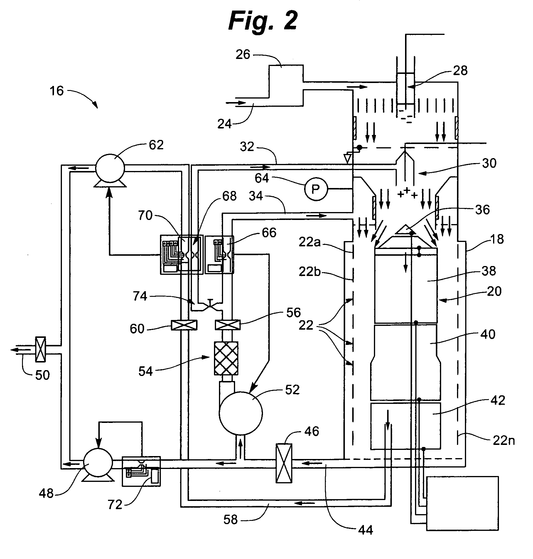
[0039]Turning now to the drawings, there is shown in FIG. 2 the structural components of an aerosol particle spectrometer 16 constructed in accordance with the present invention. Primary structural components include a housing 18 and two electrode assemblies or configurations inside the housing: a center electrode assembly 20, and an assembly of multiple annular collector electrodes 22a through 22n arranged in an axially extending series, spaced apart from each other and electrically isolated from each other. Collector electrodes 22 are concentric with and surround the center electrode assembly.

[0040]Conduits associated with housing 18 guide a combination of aerosol and other gaseous flows into and out of the housing. An aerosol entry conduit 24 receives an incoming aerosol at a rate of about 10 liters per minute, at approximately atmospheric pressure. A cyclone 26 near the entry conduit removes larger particles from the aerosol, for example, particles with diameters exceeding 1 mic...


PUM

PropertyMeasurementUnit
diametersaaaaaaaaaa
resistancesaaaaaaaaaa
travel timeaaaaaaaaaa

Abstract

An aerosol particle spectrometer utilizes a high voltage central electrode and a series of annular, axially arranged collector electrodes maintained at ground, for collecting positively charged particles suspended in an aerosol flowing between the electrodes. Each collector electrode provides current to an integrating electrometer including circuitry that rapidly charges and discharges the integrating capacitor during a brief reset cycle, to generate accurate particle characterizing information based on low currents, with high bandwidth and high dynamic range, virtually in real time.

Description

BACKGROUND OF THE INVENTION[0001]The present invention relates to devices for measuring electrical currents, and more particularly to integrating electrometers for measuring fluctuating currents. The invention further relates to instruments that use integrating electrometers to measure electrical currents to generate particle concentration distributions based on electrical mobility.[0002]Since the late 1960s, those skilled in the art have relied on electrical mobility in a variety of instruments for counting and sizing the particles in aerosols, i.e. suspensions of particles in gaseous media. One such instrument is shown schematically in FIG. 1. An aerosol including a polydisperse particulate suspension is introduced into a cylindrical housing 1 at an entrance 2 where an electrical charge is applied to the particles. A sheath flow of filtered air is introduced to the housing through a conduit 3. A cylindrical center electrode 4 is maintained at a high voltage to attract the charged ...

Claims


Application Information

Patent Timeline
Patent Type & Authority Patents(United States)
IPC IPC(8): G01R29/12G01N15/10G01R19/00G01R22/06G01T1/17
CPCG01N15/1031G01R22/06G01N15/10G01R19/00G01R19/165G01R19/16566G01T1/17
Inventor MIRME, AADU
Owner MIRME AADU
Why Eureka
Try Eureka