Wafer-level surface acoustic wave filter package with temperature-compensating characteristics

a surface acoustic wave and filter package technology, applied in the field of surface acoustic wave devices, can solve the problems of high frequency drift, affecting the performance of the filter package, and requiring a certain amount of space clearance, so as to prevent the application of saws that may require a very steep frequency response and other problems, to achieve the effect of reducing the cost of the filter packag

Active Publication Date: 2007-06-12
TRIQUINT
View PDF19 Cites 39 Cited by
  • Summary
  • Abstract
  • Description
  • Claims
  • Application Information

AI Technical Summary

Benefits of technology

[0007]A SAW filter is fabricated for providing desirable temperature characteristics. The filter includes a piezoelectric substrate bonded to a carrier substrate, wherein the coefficient of thermal expansion of the carrier substrate is less than the coefficient of thermal expansion of the piezoelectric substrate. Interdigital transducers are formed on the piezoelectric substrate bonded on the carrier substrate so as to form a SAW composite die structure. A cap substrate having a coefficient of thermal expansion similar to that of the carrier substrate is bonded to the SAW composite die structure for enclosing the interdigital transducers. Signal pads formed on the cap substrate are connected to input and output pads of the interdigital transducer. Metallic or non-conductive sealing pads formed on the surface of the piezoelectric substrate bonds the SAW composite die structure to the cap substrate.
[0008]A method aspect of the invention may include manufacturing a wafer level packaged SAW filter by bonding

Problems solved by technology

This high frequency drift would preclude some of the SAW applications that may require a very steeply shaped frequency response.
Chip and wire SAW packages have a disadvantage in that they require a certain amount of space clearance for bonding wire to the package signal pads.
However, an

Method used


Image

  • Wafer-level surface acoustic wave filter package with temperature-compensating characteristics
  • Wafer-level surface acoustic wave filter package with temperature-compensating characteristics
  • Wafer-level surface acoustic wave filter package with temperature-compensating characteristics

Examples


Embodiment Construction

[0024]The present invention will now be described more fully hereinafter with reference to the accompanying drawings, in which preferred embodiments of the invention are shown. This invention may, however, be embodied in many different forms and should not be construed as limited to the embodiments set forth herein. Rather, these embodiments are provided so that this disclosure will be thorough and complete, and will fully convey the scope of the invention to those skilled in the art. Like numbers refer to like elements throughout, and prime notation is used to indicate similar elements in alternate embodiments.

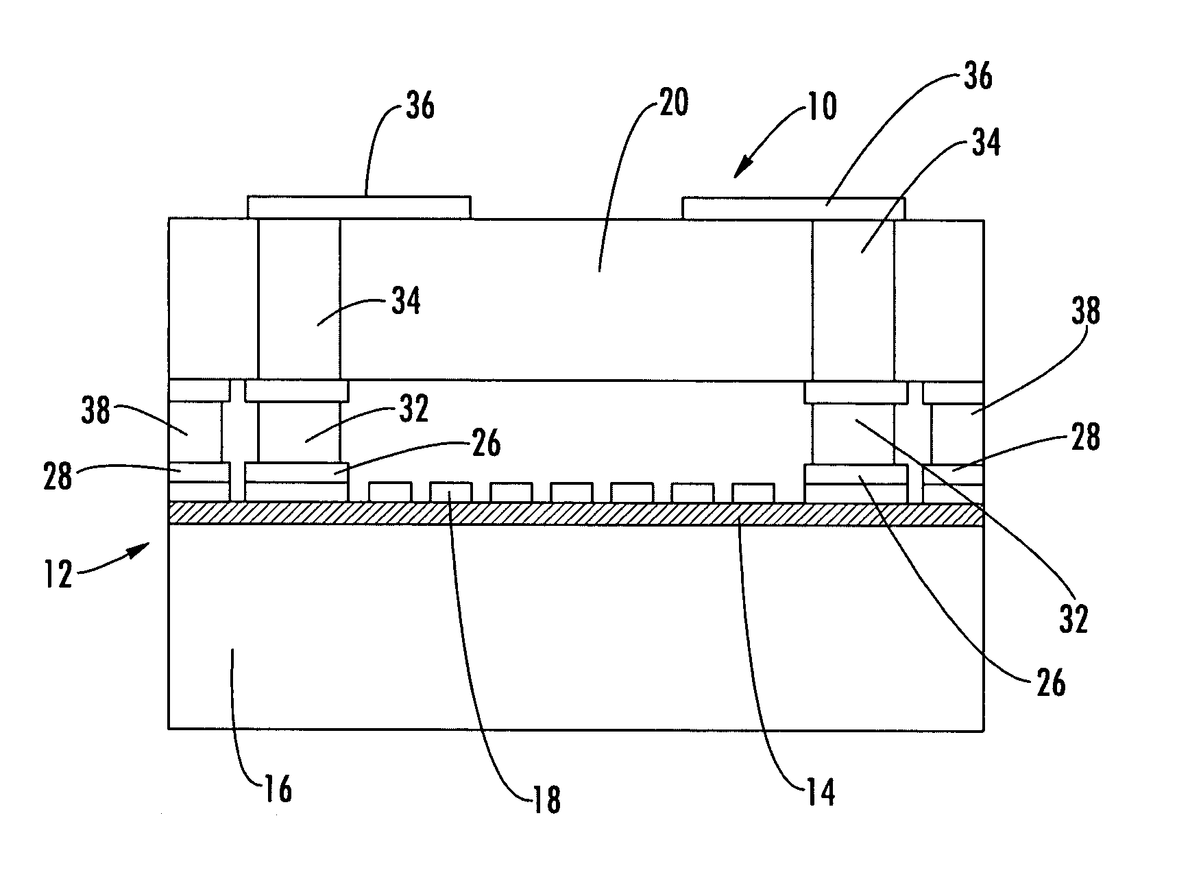
[0025]Referring initially to FIGS. 4 and 5, first 10 and second 11 embodiments of a miniaturized SAW filter having temperature compensation characteristics are illustrated, by way of example. As herein described, the SAW filter 10, 11 includes a composite SAW die structure 12 formed by a combination of a piezoelectric substrate 14 bonded to a carrier substrate 16, wherein the...


PUM


Abstract

A SAW filter is fabricated at a wafer level for providing desirable temperature characteristics. The filter includes a piezoelectric substrate bonded to a carrier substrate, wherein the coefficient of thermal expansion of the carrier substrate is less than the coefficient of thermal expansion of the piezoelectric substrate. Interdigital transducers are formed on the piezoelectric substrate so as to form a SAW composite die structure. A cap substrate having a coefficient of thermal expansion similar to that of the carrier substrate is bonded to the SAW composite die structure for enclosing the interdigital transducers. Plated vias form signal pad interconnects to input and output pads of the interdigital transducer and a sealing pad formed on the surface of the piezoelectric substrate bonds the SAW composite die structure to the cap substrate.

Description

CROSS-REFERENCE TO RELATED APPLICATIONS[0001]This application claims the benefit of U.S. Provisional Application No. 60 / 496,230, filed Aug. 19, 2003, of which is hereby incorporated herein in its entirety by reference.FIELD OF THE INVENTION[0002]The present invention relates to surface acoustic wave devices useful for applications in wireless communications.BACKGROUND OF THE INVENTION[0003]Surface Acoustic Wave (SAW) devices, on account of their small size, low cost and ease of mass production, have been widely accepted in many applications such as cellular phones, wireless LANs, and cellular base stations. Typically, a SAW device includes transducers and / or reflectors disposed on a surface of a piezoelectric substrate. FIG. 1a illustrating a typical SAW resonator filter comprising transducers and reflectors. The transducers, composed of metalized interdigitated electrodes, are used for the generation and detection of surface acoustic waves. The electrode widths and spacing determin...

Claims


Application Information

Patent Timeline
IPC IPC(8): H03H9/00H03H9/10
CPCH03H3/08H03H9/02559H03H9/02834H03H9/1071
Inventor CARPENTER, CHARLESCHOCOLA, JACKLIN, KEVIN K.WELSH, PHILLIP
Owner TRIQUINT
Why Eureka
Try Eureka