Dynamic control system for power sub-network

a technology of dynamic control system and power subnetwork, applied in the direction of electric variable regulation, process and machine control, instruments, etc., can solve the problems of increasing resistiveness, limiting the current being carried over the transmission line, and reducing the voltage at the location of consumers, so as to optimize the electricity consumption of consumers and reduce the consumption of electricity. , the effect of reducing the electrical load

Active Publication Date: 2007-06-12
COSTA BRIAN
View PDF7 Cites 58 Cited by
  • Summary
  • Abstract
  • Description
  • Claims
  • Application Information

AI Technical Summary

Benefits of technology

[0025]Clearly, it would also be beneficial to provide a mechanism for the external entities to force the turning off of outlets and circuits as necessary. By communicating information such as the existence of a power disturbance that requires all non-essential power consumption be stopped, and assuming a policy that specifies rules that would cause the disconnection of outlets identified as “non-essential”, and thus to remove their load from the cumulative electrical load, this system allows the utility service to effect a significant reduction in the electrical load in a very short time-frame through an automated means while respecting the preferences of the electricity consumers.
[0026]Additionally, as electrical utilities are moving to demand pricing, this invention can be used to optimize the consumer's electricity consumption. Assuming a demand pricing system where the current price of electricity is provided to the system implementing the invention, and a policy that specifies the turning off of non-essential outlets as electricity prices increase and the turning on of desirable outlets when prices decrease, the invention provides a system that decreases the consumption of electricity as the demand price increases, and visa-versa in an optimal, automated process.

Problems solved by technology

These devices typically react to increases in heat from the overloading transmission line and become increasingly resistive to current flow as the temperature of the transmission line increases.
Use of devices like these limits the current being carried over the transmission line, but results in either parallel transmission lines having to carry more current to meet effective demand, or in the consumer experiencing decreased voltage at their location.
Decreased voltage at the consumer's site is unacceptable since it can damage voltage sensitive equipment that is expecting the voltage of the electrical service to remain within reasonably tight acceptable limits.
Unfortunately this approach has two negative side effects.
First, when one of the parallel transmission lines between the producers and the consumers of electrical current is disconnected, whether intentionally or due to a fault, it places a greater current burden on the remaining parallel transmissions lines.
If not controlled properly, disconnecting transmission lines that are overloaded can thus result in a cascading failure of the entire transmission system as the same total current is attempted to be carried over an increasingly reduced number of available transmission lines.
However, this approach to addressing the problem suffers from the fact that the granularity at which the electrical grid can prune itself is extremely coarse.
This approach faces several challenges including resistance at the state and local regulatory levels, significant expense, and difficulty gaining right of way for expansion of the transmission system.
With demand pricing, there is a financial disincentive to using power during high use periods.

Method used


Image

  • Dynamic control system for power sub-network
  • Dynamic control system for power sub-network
  • Dynamic control system for power sub-network

Examples


Embodiment Construction

[0044]1. General Embodiment

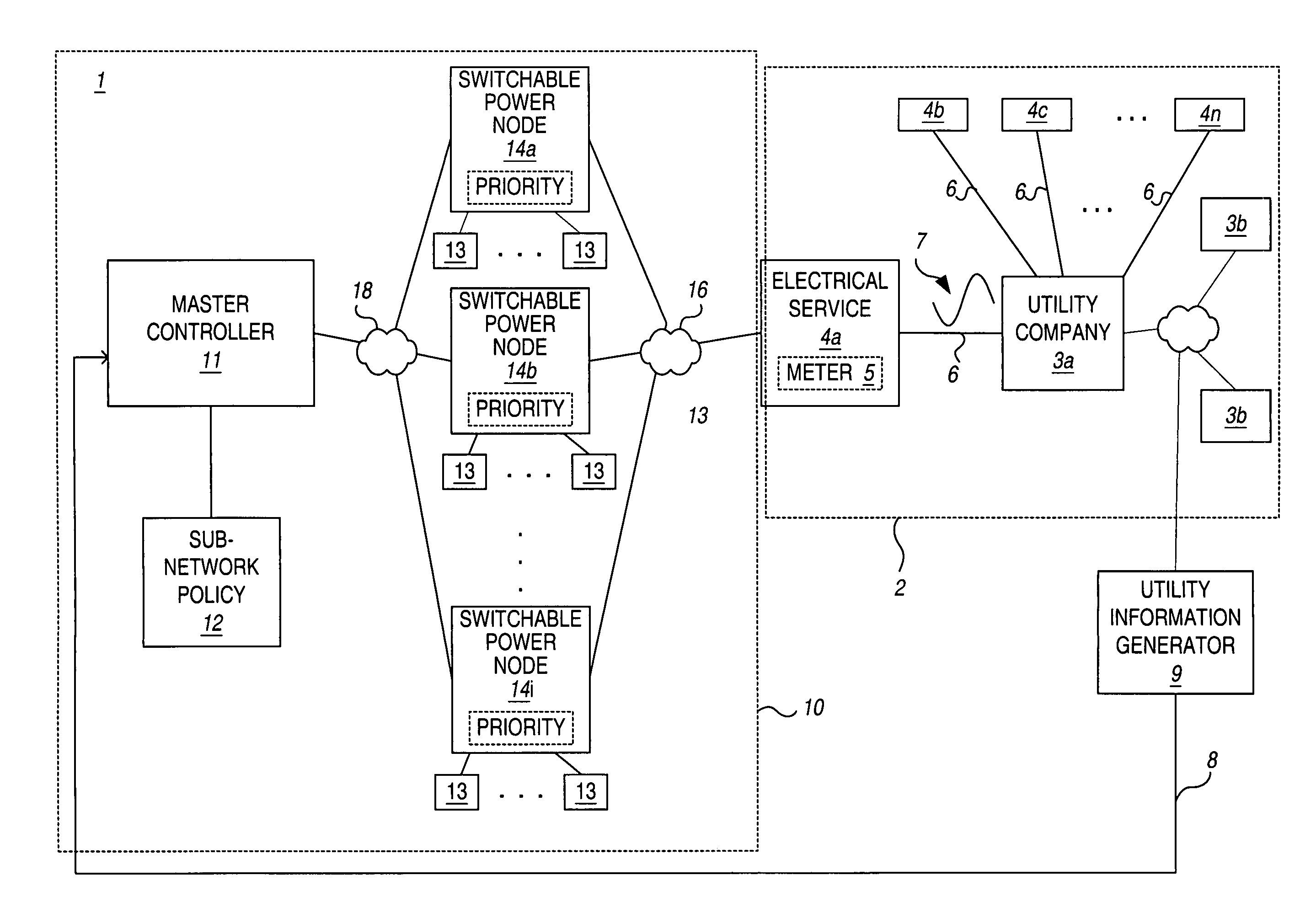
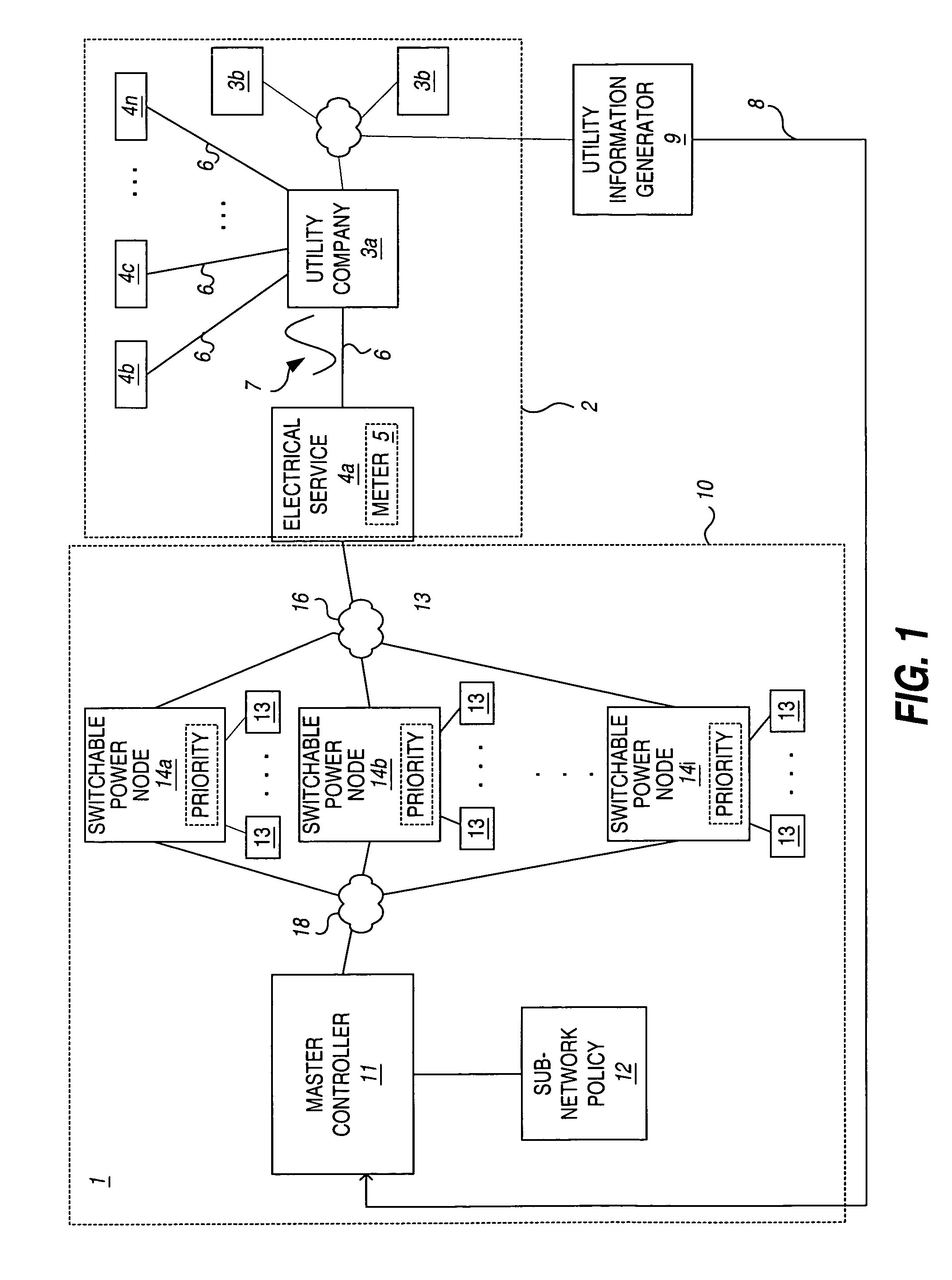
[0045]Turning now to the drawings, FIG. 1 is a block diagram of a system 1 that utilizes a dynamic power control system 10 in accordance with the invention. In this system 1, a utility company 3 services a power grid 2. It will be understood that there may be and typically are many utility companies 3a–3m servicing a given power grid 2. The utility company 3a provides electrical service to a plurality of entities 4a–4n through an electrical service unit such as a power meter 5. More particularly, the utility company 3a supplies power 7 over regional and local power lines 6 up to and including the electrical service units 4a–4n. A power sub-network 10 distributes power beyond the electrical service unit 4a over a sub-network of power lines 16 (e.g., premises wiring). The use of power within the power sub-network 16 can be dynamically controlled using the dynamic power control system 10 of the invention.

[0046]Implementation of the dynamic power control syste...


PUM


Abstract

A dynamic power control system for controlling power utilization on a local level in a power sub-network of a power grid is presented. The power sub-network is configured with switchable power nodes, each having a switch element that operates to switch coupling and uncoupling of first and second subsets of power lines in the sub-network. A sub-network controller monitors utility information that is associated with one of a plurality of switch state configurations of the respective switch states of the switchable power nodes in the power sub-network, and effects the switch states of the switchable power nodes to comply with the switch state configuration associated with the received utility information.

Description

BACKGROUND OF THE INVENTION[0001]The present invention relates generally to power utilization and more particularly to a method and apparatus for controlling power utilization in a power sub-network of a power grid based on external global power parameters.[0002]Large-scale electrical power distribution occurs over what is known in the industry as a power grid. More particularly, a power grid is an expansive network of high-voltage power transmission lines interconnected at hundreds of power generating stations and distribution substations. The stations and substations are typically owned by various utility companies, which manage distribution of power to various sectors of the grid, including distribution of power to consumers over lower-voltage power lines that are stepped-down via transformers. The substations essentially operate as power hubs, directing current from branches with power surplus to branches needing additional power. The power substations thus operate to attempt to...

Claims


Application Information

Patent Timeline
Patent Type & Authority Patents(United States)
IPC IPC(8): G05D3/12
CPCH02J3/14H02J13/0017H02J2003/146Y02B70/3225Y04S20/222Y04S20/224H02J2310/64H02J13/00006Y04S50/10
Inventor COSTA, BRIAN
Owner COSTA BRIAN
Why Eureka
Try Eureka