Correlating power signatures with automated equipment

a technology of power signatures and automated equipment, applied in the field of methods and systems, can solve the problems of time-consuming and hence costly procedures for customer engineers, and achieve the effect of facilitating a quality control tes

Inactive Publication Date: 2007-06-12
IBM CORP
View PDF26 Cites 13 Cited by
  • Summary
  • Abstract
  • Description
  • Claims
  • Application Information

AI Technical Summary

Benefits of technology

[0013]In a preferred embodiment of the invention, the current monitor is only temporarily attached to the equipment device to facilitate a quality control test prior to shipment of the device to the cu

Problems solved by technology

Connecting test equipment for each and every single electrical-mechanical component when a system failure occurs is a time consuming and hence cost

Method used


Image

  • Correlating power signatures with automated equipment
  • Correlating power signatures with automated equipment
  • Correlating power signatures with automated equipment

Examples


Embodiment Construction

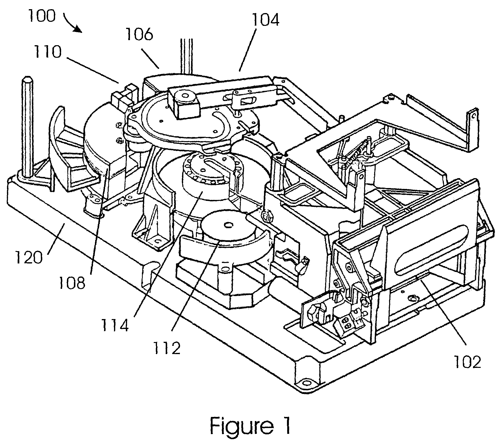
[0030]FIG. 1 depicts a typical reel-to-reel tape drive 100. Tape drive 100 may be any one of a family of tape drives using a single-reel tape cartridge, such as the IBM 3480, IBM 3490, IBM 3590, and Linear Tape Open (LTO) tape drives. Cartridge loader 102 receives the single-reel tape cartridge and threader 104 threads the leader-block of the tape around the tape guides 106 and 108, and around the tape tension transducer 112, and into the take-up reel 114. Tape guides 106 and 108 support the tape as the tape flies over the magnetic tape head 110. All of these components are supported by base plate 120.

[0031]One single-reel magnetic tape cartridge is documented in U.S. Pat. No. 4,426,047; entitled “Single Reel Tape Cartridge,” by Richard and Winarski, which is incorporated by reference in its entirety. The control of reel-to-reel tape drive 100 is documented in U.S. Pat. No. 4,125,881; entitled Tape Motion Control for Reel-to-Reel Drive, by Eige, et-al, which is incorporated in its e...


PUM


Abstract

A method and system for monitoring the activity of a system of one or more electro-mechanical components that receive electrical current from a power supply. The method and system samples an actual current supplied to the electro-mechanical component from the power supply. Next, the method and system reads a theoretical current for the activity of the system. A statistical value is computed from comparing the actual current and the theoretical current. This statistical value is compared to upper and lower threshold values. Depending upon this comparison, the system issues various output messages. Further, if this comparison indicates that one of the electro-mechanical components is failing, the method and system will shut that component down.

Description

FIELD OF THE INVENTION[0001]The present invention relates to the field of methods and systems used to test and monitor the current consumption of an electrical-mechanical device. More specifically, the present invention relates to a method and apparatus to perform correlation and statistical analysis of the time varying power consumption of a system of electrical-mechanical devices receiving power from one or more power supplies.BACKGROUND OF THE INVENTION[0002]There is a great need for testing and monitoring the operation of electrical-mechanical components of systems. For corporations that produce systems with electrical-mechanical components, it is necessary to test the manufactured systems for defects before shipping the systems to customers, thereby increasing profitability and customer satisfaction. The industries that utilize these electrical-mechanical components want to minimize machine down time for their customers. Having devices and systems that can characterize the oper...

Claims


Application Information

Patent Timeline
IPC IPC(8): G06F11/30G01M7/00G01R19/25
CPCG06F1/3215G06F1/3221G06F1/325G06F1/3268G11B15/026G11B15/18G11B15/689Y02B60/1246Y02D10/00
Inventor TODD, DOUGLAS WALLACEHELLMAN, DIANA JOYCEMCINTOSH, MICHAEL PHILIPPEIPELMAN, JASON LEE
Owner IBM CORP
Why Eureka
Try Eureka