Planar electrochemical device assembly

Inactive Publication Date: 2007-06-19
RGT UNIV OF CALIFORNIA
View PDF70 Cites 26 Cited by
  • Summary
  • Abstract
  • Description
  • Claims
  • Application Information

AI Technical Summary

Benefits of technology

[0034]Another object of the invention is to provide an electrochemical cell that is durable, reliable and is inexpensive to manufacture.
[0035]St

Problems solved by technology

Unfortunately, most metals are not stable at the high operating temperatures and oxidizing environment of conventional fuel cells and become converted very quickly to brittle oxides.
In solid oxide fuel cells, component durability is most problematic at the air electrode where oxidation can take place.
In other solid-state electrochemical devices, such as oxygen generators, both electrodes may be in an oxidizing environment during operation of the device, and so both may face this problem.
These materials tend to be expensive and still have a limited life in high temperature and high oxidation conditions.
However, it has also been observed that the resistance of electrolyte layers that are deposited as very thin films is very low at intermediate temperatures ranging between 500° C. and 800° C. Intermediate operational temperatures will allow the use of comparatively less expensive materials to construct the cell and lower the thermal energy requirements.
Furthermore, many of these application methods are complex and expensive techniques and the high operating costs as well as the cost of production equipment present a significant barrier to commercialization.
However, tubular designs provide less power density than planar designs due to the relatively long current path that results in a substantial resistive power loss that is inherent in the d

Method used


Image

  • Planar electrochemical device assembly
  • Planar electrochemical device assembly
  • Planar electrochemical device assembly

Examples


Example

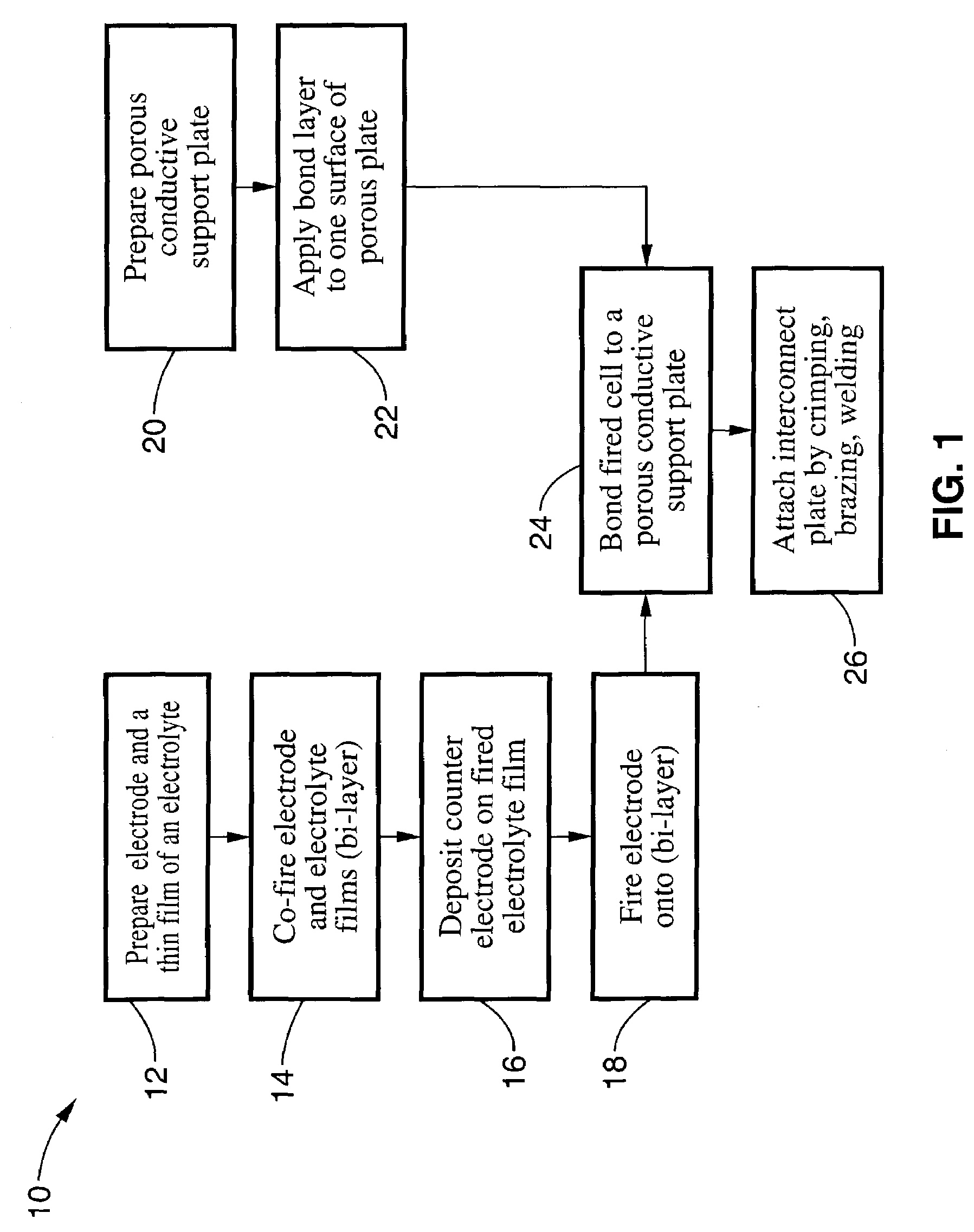
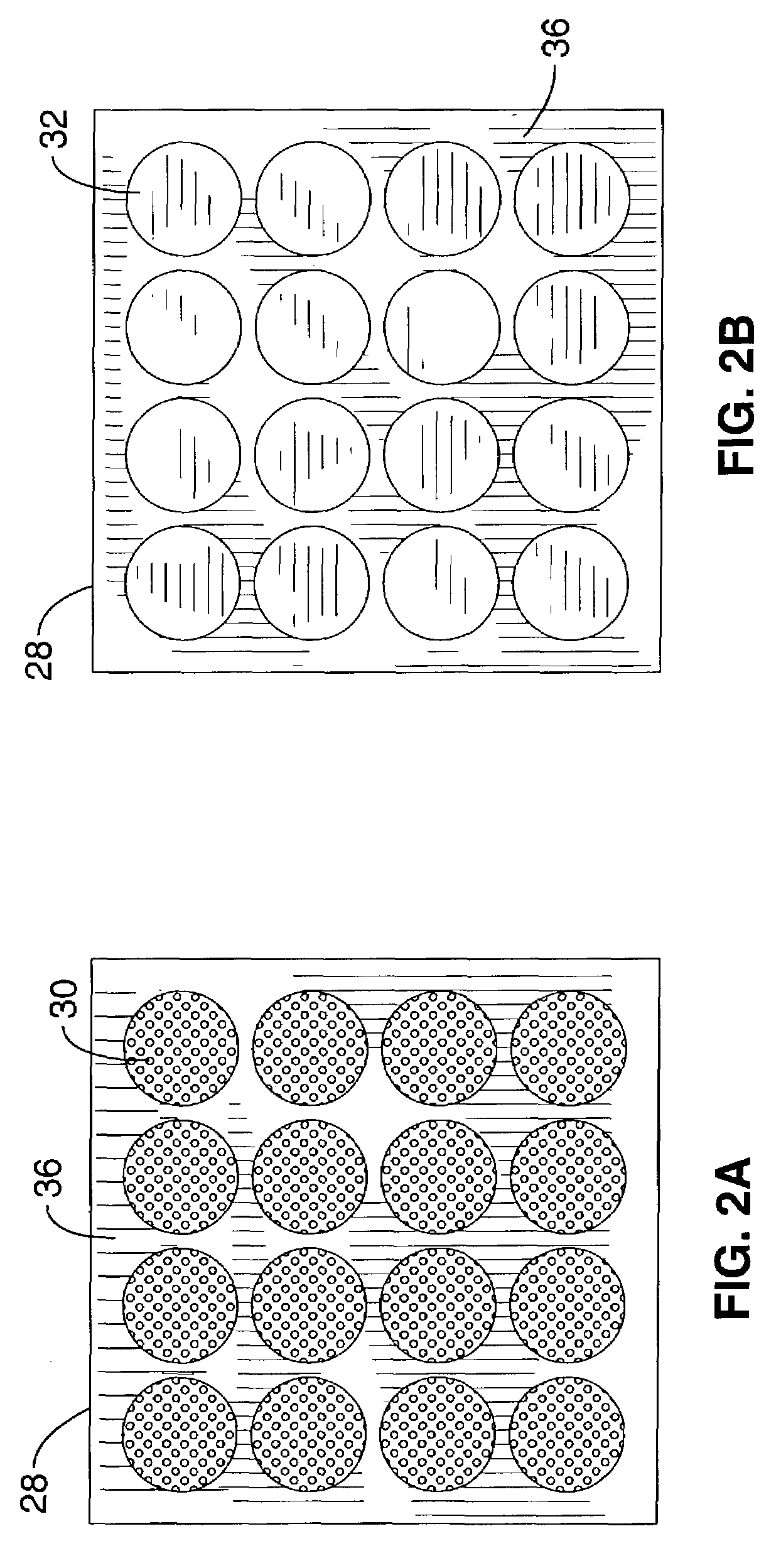
[0048]Referring more specifically to the drawings, for illustrative purposes the present invention is embodied in the method shown in FIG. 1 and the devices generally shown in FIG. 2 through FIG. 8. It will be appreciated that the apparatus may vary as to configuration and as to details of the parts, and that the method may vary as to the specific steps and sequence, without departing from the basic concepts as disclosed herein.

[0049]Referring first to FIG. 1, an embodiment of a method of fabricating an electrochemical device assembly according to the present invention will now be described. In the embodiment that will be described, a fuel cell will be used as an exemplary electrochemical device. It will be appreciated, however, that other types of electrochemical devices can be fabricated in accordance with method of the present invention.

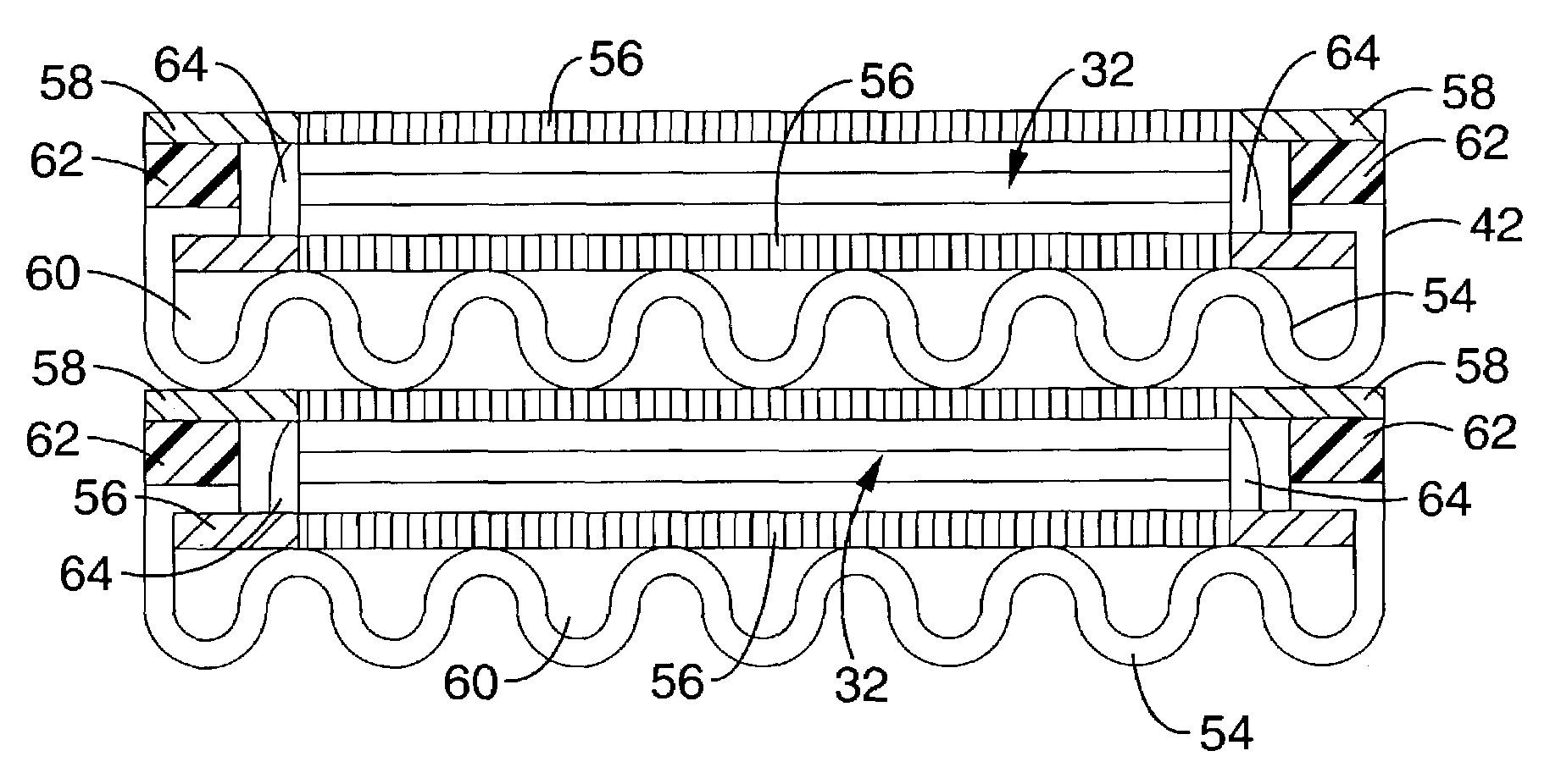
[0050]In the method illustrated in FIG. 1, a prefabricated electrochemical device is bonded to a porous electrically conductive support plate by ...


PUM

PropertyMeasurementUnit
Fractionaaaaaaaaaa
Electrical conductivityaaaaaaaaaa
Electrical conductoraaaaaaaaaa

Abstract

A pre-fabricated electrochemical device having a dense electrolyte disposed between an anode and a cathode preferably deposited as thin films is bonded to a porous electrically conductive support. A second porous electrically conductive support may be bonded to a counter electrode of the electrochemical device. Multiple electrochemical devices may be bonded in parallel to a single porous support, such as a perforated sheet to provide a planar array. Planar arrays may be arranged in a stacked interconnected array. A method of making a supported electrochemical device is disclosed wherein the method includes a step of bonding a pre-fabricated electrochemical device layer to an existing porous metal or porous metal alloy layer.

Description

CROSS-REFERENCE TO RELATED APPLICATIONS[0001]This application claims priority from U.S. provisional application Ser. No. 60 / 449,095 filed on Feb. 20, 2003, incorporated herein by reference, and from U.S. provisional application Ser. No. 60 / 375,515 filed on Apr. 24, 2002, incorporated herein by reference.STATEMENT REGARDING FEDERALLY SPONSORED RESEARCH OR DEVELOPMENT[0002]This invention was made with government support under Grant (Contract) No. DE-AC03-76F00098 awarded by the United States Department of Energy. The government has certain rights to this invention.INCORPORATION-BY-REFERENCE OF MATERIAL SUBMITTED ON A COMPACT DISC[0003]Not ApplicableBACKGROUND OF THE INVENTION[0004]1. Field of the Invention[0005]This invention pertains generally to solid-state electrochemical devices, and more particularly to an electrochemical device support structure and an illustrative solid oxide fuel cell with exceptional electrochemical performance.[0006]2. Description of Related Art[0007]Solid-s...

Claims


Application Information

Patent Timeline
IPC IPC(8): H01M4/00H01M2/02H01M8/00H01M8/10C25B9/00H01LH01M2/08H01M6/00H01M6/46H01M8/02H01M8/12H01M8/24
CPCH01M8/0297H01M8/1226H01M8/2425H01M8/0202Y10T29/4911Y02E60/521Y02E60/525Y10T29/49114H01M8/2428Y02E60/50Y02P70/50H01M8/2483
Inventor JACOBSON, CRAIG P.VISCO, STEVEN J.DE JONGHE, LUTGARD C.
Owner RGT UNIV OF CALIFORNIA
Why Eureka
Try Eureka