
Method for searching pilot signals to synchronize a CDMA receiver with an associated transmitter

Inactive Publication Date: 2007-06-19
IPR LICENSING INC
View PDF7 Cites 5 Cited by
  • Summary
  • Abstract
  • Description
  • Claims
  • Application Information

AI Technical Summary

Benefits of technology

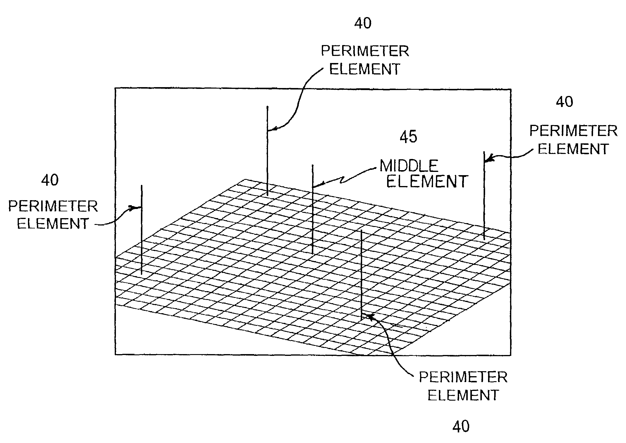
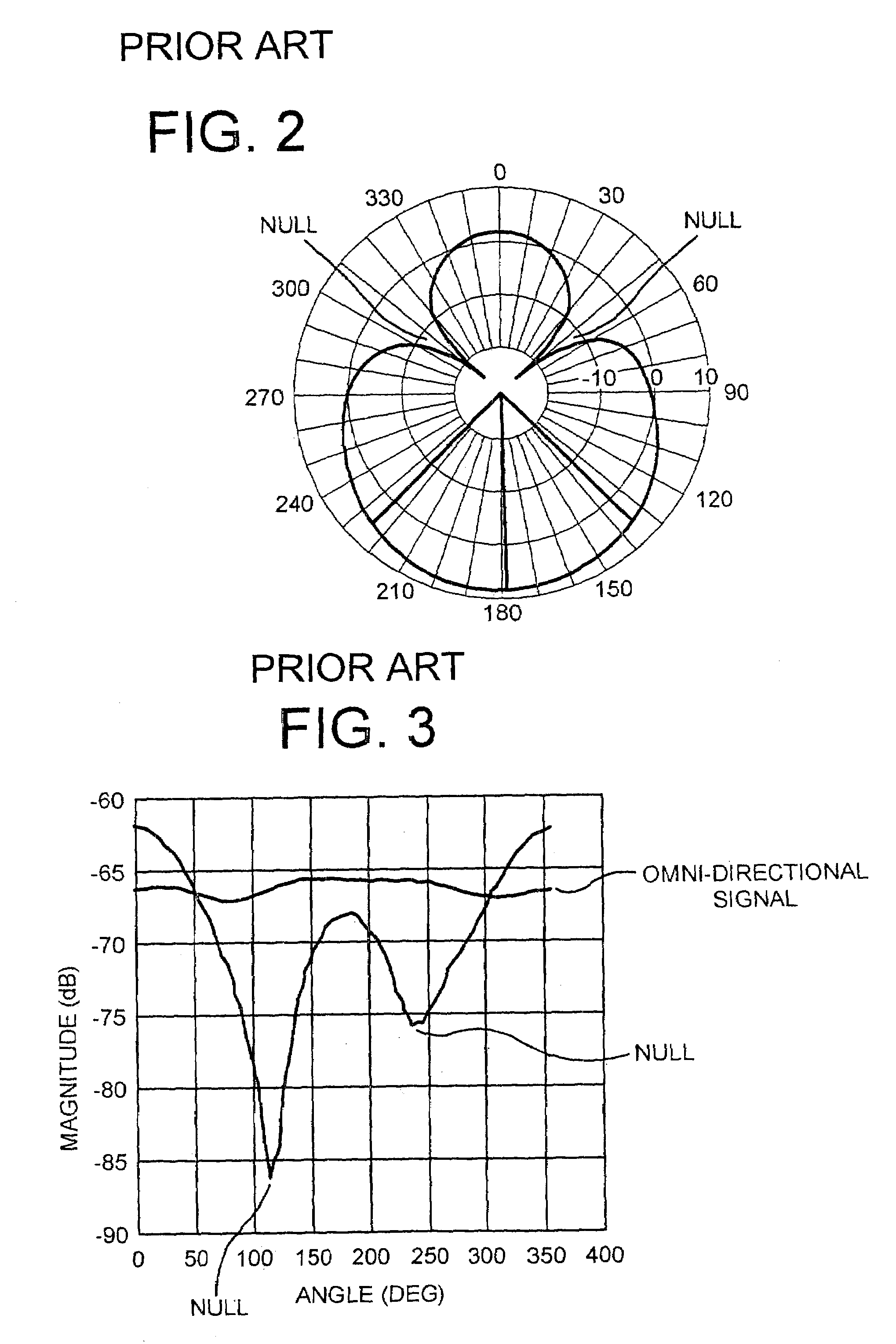
[0022]The present invention is directed to a method for synchronizing a CDMA receiver to a transmitted pilot signal when an adaptive antenna system having circuit elements associated with its radiating elements such that some of the antenna properties are controlled by a received signal is utilized to receive transmitted data. An attractive method of reducing the synchronization delay pattern is to adapt a receiving antenna system between a 360° reception angle pattern (i.e., an omni-directional pattern) and a fixed reception angle (i.e., a directional pattern). This is accomplished by permitting the receiver to identify the pilot signal having the greatest magnitude, as a result of permitting the receiver to minimize interference from other pilot signals by steering antenna pattern nulls toward other transmitters.
[0025]The method of the invention eliminates the need to search all possible PN offsets during synchronization of the CDMA receiver with the transmitted pilot signal. The method eliminates the search of additional parameters, such as the null steering parameter. The search over the PN offsets, the azimuth angle and the null steering is eliminated. As a result, synchronization delay is minimized and a rapid acquisition of the transmitted pilot signal is achieved.

Problems solved by technology

In some instances, a pilot channel is not used on the reverse link based on the impracticality of each mobile station broadcasting its own pilot sequence.
Such services were at first typically considered to be the exclusive province of the businessman because of high subscriber costs.
However, there is still no widely available satisfactory solution for providing low cost, broad geographical coverage, high speed access to the Internet, private intranets, and other networks using the existing wireless infrastructure.
For one, the typical manner of providing high speed data service in the business environment over the wireline network is not readily adaptable to the voice grade service which is available in most homes or offices.
Additionally, such standard high speed data services do not lend themselves well to efficient transmission over standard cellular wireless handsets.
Although xDSL and Integrate Services Digital Network (ISDN) networks were known at the time that cellular systems were originally deployed, for the most part, there is no provision for providing higher speed ISDN or xDSL grade data services over cellular networks.
Unfortunately, in wireless environments, access to channels by multiple subscribers is expensive and there is competition for them.
This is quite different from the traditional environment for data transmission, in which the wireline medium is relatively inexpensive to obtain, and is therefore not typically intended to be shared.
Current wireless standards in widespread use such as CDMA do not provide an adequate structure with which to support the most common activities, such as web page browsing.
In practicality, this limit is difficult to attain, and 20 or 30 simultaneous users are typically active at one time.
Furthermore, existing CDMA systems require certain operations before a channel can be used.
Such an iterative search over the PN offsets, the azimuth angle and the null steering is a slow and time consuming process which produces a noticeable synchronization delay to a user of a subscriber unit due to the necessity to search over the additional constraints.

Method used


Image

  • Method for searching pilot signals to synchronize a CDMA receiver with an associated transmitter
  • Method for searching pilot signals to synchronize a CDMA receiver with an associated transmitter
  • Method for searching pilot signals to synchronize a CDMA receiver with an associated transmitter

Examples


Embodiment Construction

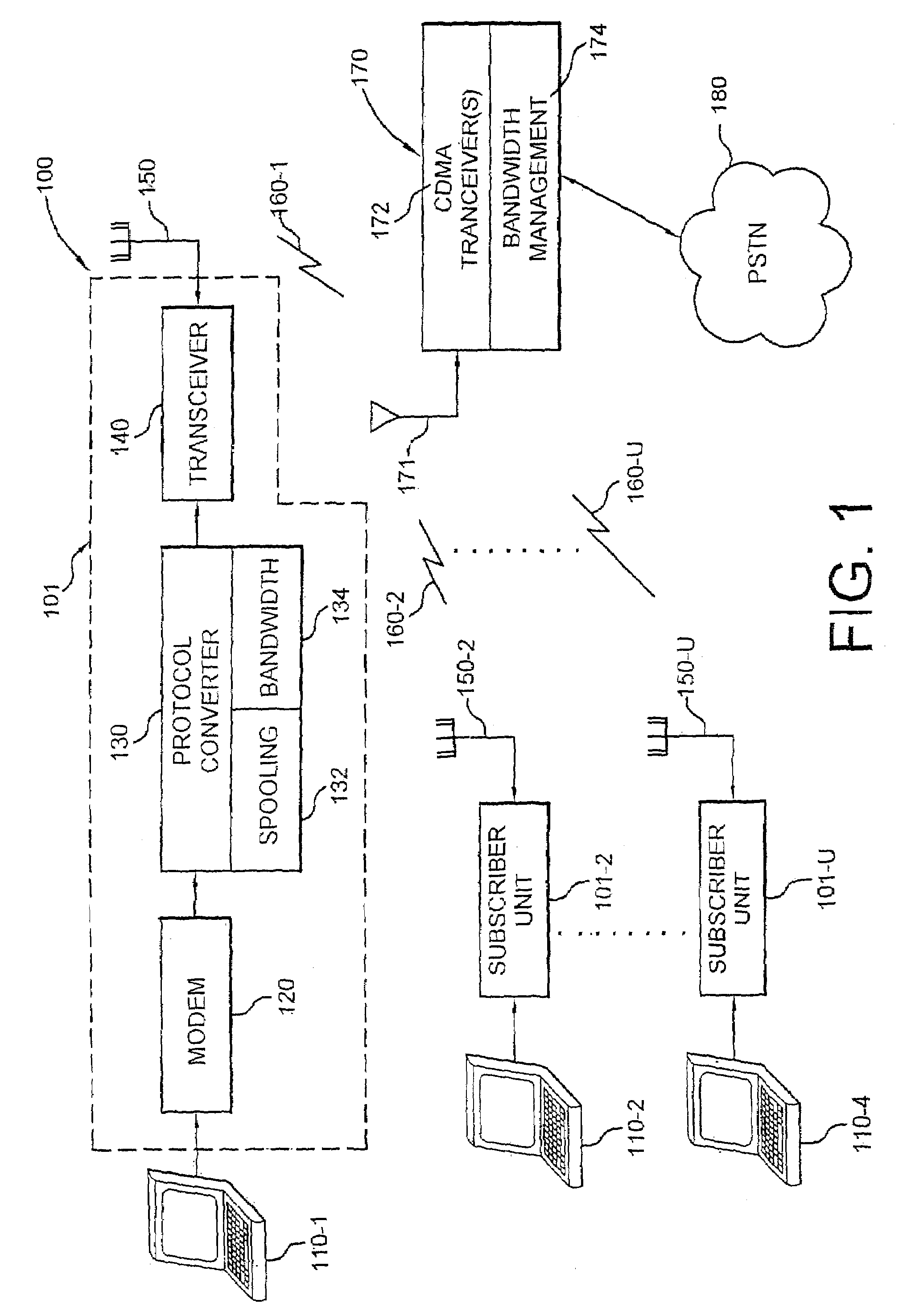
[0035]FIG. 1 is a block diagram of a wireless communication system 100 in which a receiving antenna is adapted between an omni-directional pattern and a directional pattern. The system 100 includes two different types of components, such as subscriber units 101-1, 101-2, . . . , 101-u (collectively, the subscriber units 101) and one or more base stations 170. The subscriber units 101 and base stations 170 cooperate to provide the functions necessary in order to provide wireless data services to a portable computing device 110 such as a laptop computer, portable computer, personal digital assistance (PDA) or the like associated with a subscriber unit 101. The base station 170 also cooperates with the subscriber units 101 to permit the ultimate transmission of data to and from the subscriber unit 101 and the public switch telephone network (PSTN) 180. More particularly, data and / or voice services are also provided by the subscriber unit 101 to the portable computer 110 as well as one ...


PUM


Abstract

A method for synchronizing a CDMA receiver to a transmitter when an adaptive antenna is utilized to receive transmitted data, wherein a receiving antenna system is adapted between a 360° reception angle pattern (i.e., an omni-directional pattern) and a fixed reception angle (i.e., a directional pattern) by permitting the receiver to identify a pilot signal having the largest magnitude. The receiver minimizes interference from other pilot signals by steering antenna pattern nulls toward other transmitters. As a result, the time required for the receiver to acquire a valid pilot signal is significantly reduced.

Description

RELATED APPLICATION(S)[0001]This application claims the benefit of U.S. Provisional Application No. 60 / 184,363, filed Feb. 23, 2000.BACKGROUND OF THE INVENTION[0002]1. Field of the Invention[0003]The present invention generally relates to the field of data communications and processing and, more particularly, to a method for synchronizing a CDMA receiver to a transmitter when an adaptive antenna is utilized to receive transmitted data.[0004]2. Description of the Related Art[0005]Code Division Multiple Access (CDMA) modulation is a multi-user access transmission scheme in which different users of the same transmission medium overlap both in frequency and in time. This is in contrast to Frequency Division Multiple Access (FDMA) in which users overlap in time, but are assigned unique frequencies, and Time Division Multiple Access (TDMA) in which users overlap in frequency, but are assigned unique timeslots. According to CDMA, each user is assigned a unique code sequence that allows the...

Claims


Application Information

Patent Timeline
IPC IPC(8): H04B7/02H04B1/7073H04B1/707H04B1/7075H04B1/7077H04B1/7103H04B1/7117H04B7/08H04L27/00H04L27/227
CPCH04B1/7075H04B1/70775H04B7/086H04L27/2273H04W56/001H04B1/7103H04B2201/70701H04L2027/0057H04L2027/0087H04B1/7073H04B1/7117
Inventor PROCTOR, JAMES A.ROUPHAEL, ANTOINE J.HOFFMANN, JOHN E.NELSON, JR., GEORGE RODNEY
Owner IPR LICENSING INC
Learn More