Cryocooler with grooved flow straightener

a technology of flow straightener and cryocooler, which is applied in the direction of refrigeration machine, gas cycle refrigeration machine, lighting and heating apparatus, etc., can solve the problems of troublesome problems and inefficiency of operation, and achieve the effect of improving gas flow uniformity

Active Publication Date: 2007-06-26
PRAXAIR TECH INC +1
View PDF11 Cites 1 Cited by
  • Summary
  • Abstract
  • Description
  • Claims
  • Application Information

AI Technical Summary

Benefits of technology

[0005]A cryocooler comprising a pressure wave generator and a regenerator which contains heat transfer media, and having at least one flow straightener comprising a plate having a plurality of perforations and a plurality of grooves in the plate surface, and positioned to, at least one of, retain heat transfer media within the regenerator and enhance gas flow uniformity through the regenerator.
[0007]A cryocooler comprising a pressure wave generator and a thermal buffer tube, and at least one flow straightener comprising a plate having a plurality of perforations and a plurality of grooves in the plate surface and positioned to enhance gas flow uniformity through the thermal buffer tube.

Problems solved by technology

One problem with conventional cryocooler systems is the loss of effective load heat capacity and flow uniformity and the resulting heat transfer maldistribution in the regenerator portion of the cryocooler which leads to operational inefficiency.
These problems are particularly troublesome when the cryocooler is operated to provide very low temperature refrigeration such as below 40K.

Method used


Image

  • Cryocooler with grooved flow straightener
  • Cryocooler with grooved flow straightener
  • Cryocooler with grooved flow straightener

Examples


Embodiment Construction

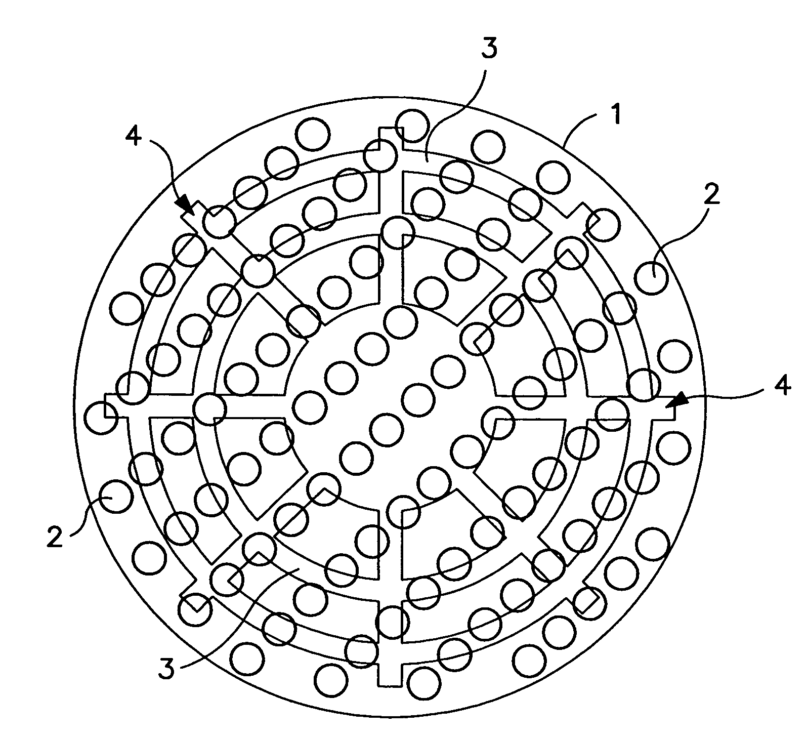
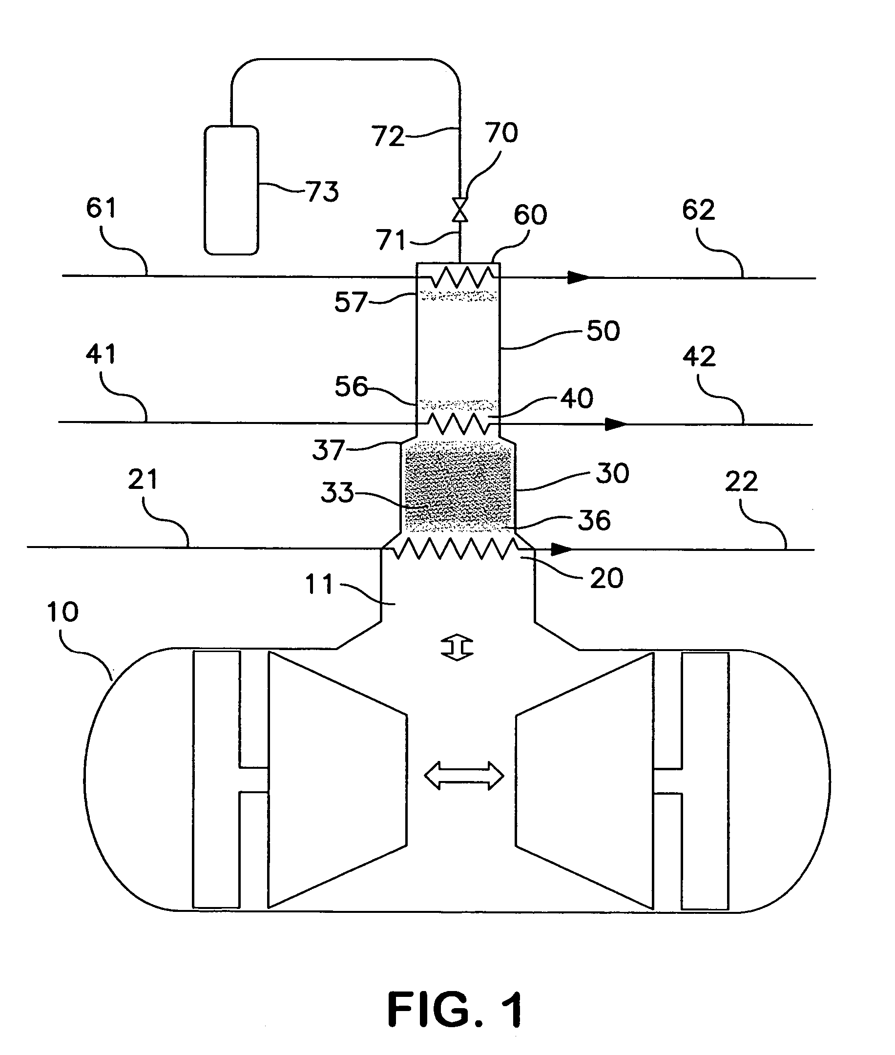
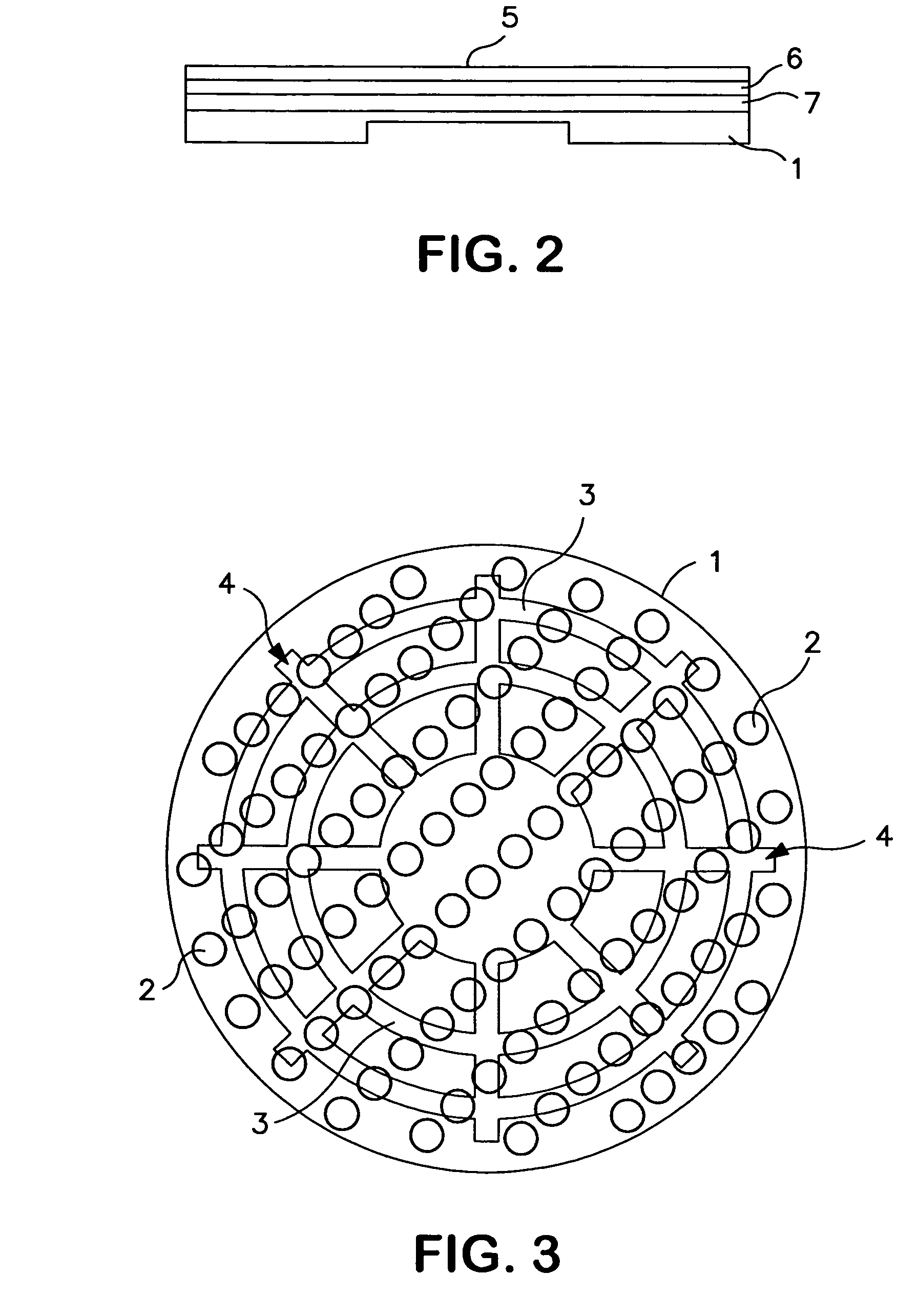
[0020]The invention will be described in greater detail with reference to the Drawings. Referring now to FIG. 1, pressure wave generator 10, which may be a compressor driven by a linear or rotary motor, generates a pulsing gas to drive a cryocooler such as the pulse tube cryocooler illustrated in FIG. 1. The pulsing working gas pulses within the pressure wave pathway which comprises the pressure wave generator, a regenerator and a thermal buffer volume. In the pulse tube type cryocooler illustrated in FIG. 1, the pressure wave pathway also includes a reservoir downstream of the thermal buffer volume. Typically the working gas comprises helium. Other gases which may be used as working gas in the practice of this invention include neon, argon, xenon, nitrogen, air, hydrogen and methane. Mixtures of two or more such gases may also be used as the working gas.

[0021]The pulsing working gas through passageway 11 applies a pulse to the hot end of the regenerator 30 thereby generating an osc...


PUM


Abstract

A cryocooler system having at least one flow straightener which has a system of grooves on its perforated surface for enhancing gas flow uniformity through the system wherein pulsing gas which does not initially pass through the flow straightener through a perforation flows along the surface of the flow straightener within a groove prior to passing through a perforation and is effectively redistributed across the surface of the flow straightener and thus the cross section of the regenerator or thermal buffer tube.

Description

TECHNICAL FIELD[0001]This invention relates generally to low temperature or cryogenic refrigeration and, more particularly, to cryocoolers for the generation of such cryogenic refrigeration.BACKGROUND ART[0002]A recent significant advancement in the field of generating low temperature refrigeration is the pulse tube and other cryocooler systems wherein pulse energy is converted to refrigeration using an oscillating gas. Such systems can generate refrigeration to very low levels sufficient, for example, to liquefy helium.[0003]One problem with conventional cryocooler systems is the loss of effective load heat capacity and flow uniformity and the resulting heat transfer maldistribution in the regenerator portion of the cryocooler which leads to operational inefficiency. These problems are particularly troublesome when the cryocooler is operated to provide very low temperature refrigeration such as below 40K.SUMMARY OF THE INVENTION[0004]One aspect of the invention is:[0005]A cryocoole...

Claims


Application Information

Patent Timeline
Patent Type & Authority Patents(United States)
IPC IPC(8): F25B9/00
CPCF25B9/145F25B9/10F25B2309/001F25B2309/003F25B2309/1415F25B2309/1421F25B2309/1424
Inventor ARMAN, BAYRAMACHARYA, ARUNHAMILTON, AL-KHALIQUE S.
Owner PRAXAIR TECH INC
Why Eureka
Try Eureka