Drive method of light-emitting display panel and organic EL display device

a technology of light-emitting display panel and drive method, which is applied in static indicating devices, electroluminescent light sources, instruments, etc., can solve the problems of substantial luminance drop, increase in power loss in constant current circuits, and deterioration of the el element, so as to reduce the electric power loss, and improve the gentle changing characteristics of the light emission luminance of the display panel

Inactive Publication Date: 2007-06-26
TOHOKU PIONEER CORP
View PDF10 Cites 13 Cited by
  • Summary
  • Abstract
  • Description
  • Claims
  • Application Information

AI Technical Summary

Benefits of technology

[0025]An object of the present invention, which was made in view of the above technical views of point, is to provide a drive method of a light-emitting display panel capable of reducing the drive electric power as well as capable of improving the gentle operation characteristics of light emission luminance generated when, for example, the light emission luminance of the display panel is changed or when the display panel starts to be lit, as described above, and to provide an organic EL display device using the drive method.
[0033]According to the display device employing the drive method, the forward direction voltages of the light-emitting elements supplied through the constant current circuits are detected so as to control the voltage output from the drive voltage source, thereby the constant current circuits for supplying constant currents to the respective EL elements can minimize the voltage drop thereof within a range in which a constant current supply operation can be secured. Accordingly, this arrangement can contribute to the reduction of an electric power loss in the constant current circuits.
[0034]When the first control aspect is employed, the voltage output from the drive voltage source is controlled at timing of shorter intervals than ordinary intervals when, for example, the light-emitting display panel starts to be lit or when the light emission luminance of the light-emitting display panel is changed, thereby the gentle changing characteristics of the light emission luminance of the display panel can be improved. Then, when the first control aspect is employed, the intervals at which the forward direction voltages of the elements are sampled and held are shortened for only a predetermined period, thereby the degree of an electric power loss caused by the sampling and holding operation can be reduced.
[0035]Further, when the second control aspect is employed, the voltage output from the drive voltage source based on the forward direction voltages of the elements is controlled only when, for example, the light-emitting display panel starts to be lit or when the light emission luminance of the light-emitting display panel is changed. In this case, the gentle changing characteristics of the light emission luminance can be improved by repeatedly controlling the voltage output from the drive voltage source a plurality of times. In this case, since the operation for sampling and holding the forward direction voltages of the elements is executed for only a predetermined period, the degree of an electric power loss caused by the sampling and holding operation can be more reduced.
[0036]Note that when the second control aspect is employed, the voltage output from the drive voltage source is controlled only when the light-emitting display panel starts to be lit or when the light emission luminance of the light-emitting display panel is changed. However, the electric deterioration with age and temperature dependency of the light-emitting elements can be compensated at the time. Accordingly, sufficient compensation characteristics can be secured in practical use.

Problems solved by technology

However, the constant current circuits are ordinarily used as shown in the figure because of the reasons that the voltage / luminance characteristics of the EL elements are unstable to a temperature change while the current / luminance characteristics thereof are stable to the temperature change, that there is a possibility that the EL elements are deteriorated by an excessive current, and the like.
When this margin is added, the amount of voltage drop is made excessive in almost all the constant current circuits, thereby a problem is arisen in that a power loss is increased in the constant current circuits.
However, the substantial luminance of the display panel cannot help being dropped because the rising-up of the light emission of the element is delayed.
Thus, a problem is arisen in that the gentle change of luminance as described above is felt unnatural by a user.
Thus, the above problem is also arisen similarly when the luminance is risen.
Furthermore, the above problem is not limited to the case in which the light emission luminance is changed while the display panel is being lit but a similar problem is also arisen when, for example, the display panel starts to be lit.
However, when the sampling hold is executed at the timing of the short intervals, a drive power necessary to the sampling hold operation and a held voltage are discharged each time the sampling hold operation is executed, thereby a power is wasted.
Therefore, when for example, the drive method is used in mobile terminals, and the like, the power of batteries are wasted, and thus this drive method is not preferable.

Method used


Image

  • Drive method of light-emitting display panel and organic EL display device
  • Drive method of light-emitting display panel and organic EL display device
  • Drive method of light-emitting display panel and organic EL display device

Examples


Embodiment Construction

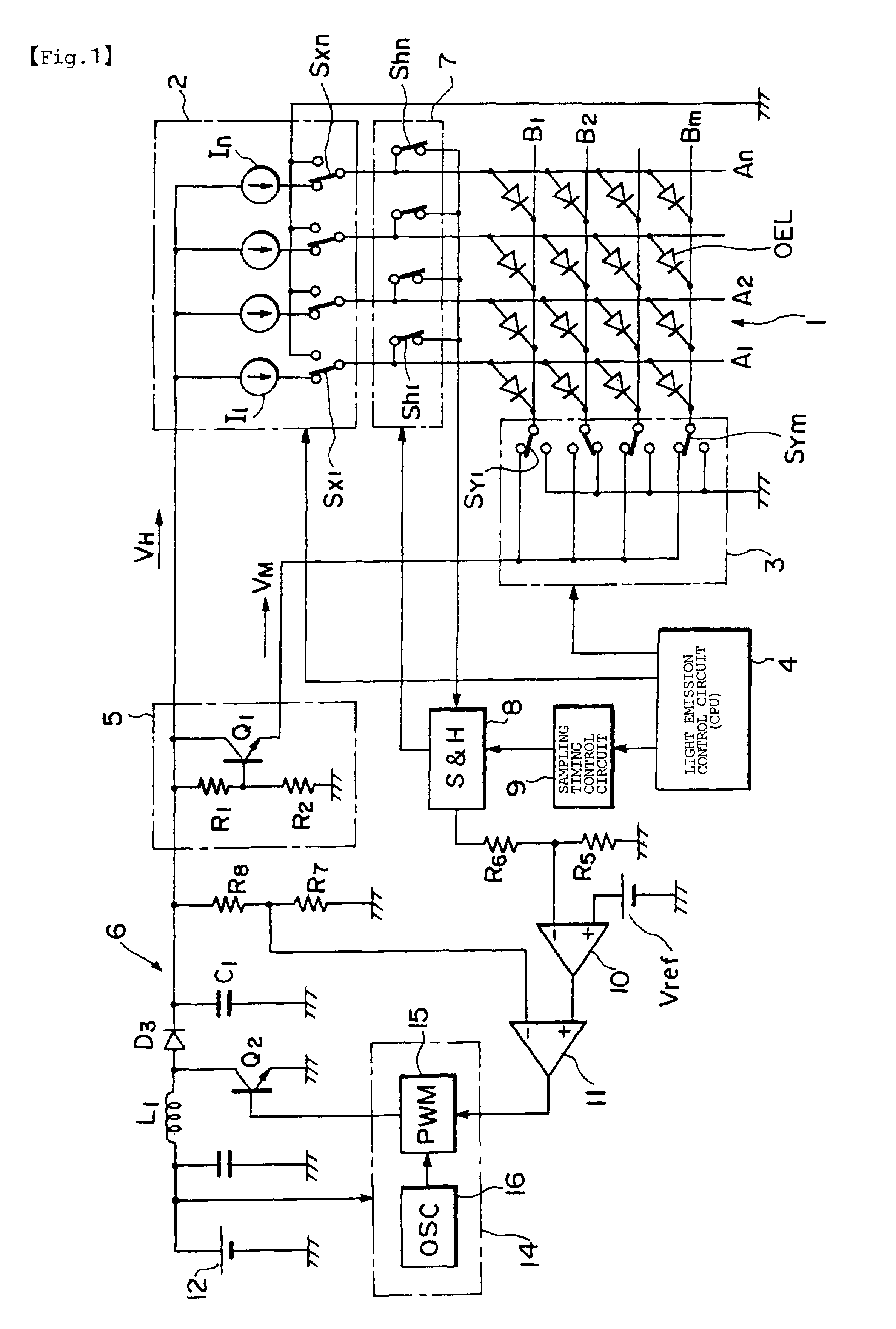
[0047]A drive unit of a light-emitting display panel according to the present invention will be explained as to a preferable embodiment thereof with reference to the figures. FIG. 1 shows a passive matrix drive system to which the present invention is applied and an example of a display panel whose light emission is controlled by the passive matrix drive system. Note that, in FIG. 1, a display panel 1, an anode line drive circuit 2, a cathode line scan circuit 3, and a light emission control circuit 4 that drive the display panel 1, and further a reverse bias voltage creation circuit 5 have the same functions as those of the respective circuits shown in FIG. 5 described above, and thus the detailed description thereof is appropriately omitted.

[0048]In the embodiment shown in FIG. 1, a sampling switch 7 is interposed between the anode line drive circuit 2 and the display panel 1. The sampling switch 7 includes switches denoted by Sh1 to Shn in correspondence to drive switches Sx1 to ...


PUM


Abstract

Light-emitting elements disposed on a light-emitting display panel are driven by constant currents, and the forward direction voltages of the light-emitting elements are obtained by a sampling / holding circuit. Then, the voltage output from a drive voltage source composed of a DC-DC converter is controlled by the forward direction voltages obtained by the sampling / holding circuit. For example, in a case in which the light emission luminance of the light-emitting display panel is changed or in other case, a sampling and holding operation is executed by the sampling / holding circuit in response to a control signal from a sampling timing control circuit at intervals shorter than ordinary intervals. With this arrangement, when light emission luminance of a light-emitting display panel is changed, the gentle changing characteristics of the light emission luminance thereof can be improved.

Description

BACKGROUND OF THE INVENTION[0001]1. Field of the Invention[0002]The present invention relates to a drive method of a light-emitting display panel using, for example, organic electroluminescence (EL) elements as light-emitting elements and to a display device using the light-emitting display panel, and more particularly, to a control technology for controlling the light-emitting luminance of the light-emitting elements.[0003]2. Description of the Related Art[0004]Attention is paid to an organic EL display as a display replacing a liquid crystal display because the organic EL display can reduce power consumption, can display an image of high quality and further can be reduced in thickness. This is because the efficiency and life of the organic EL display has been improved to a practically usable level by using an organic compound promising good light emitting characteristics for the light-emitting layers of EL elements used in the EL display.[0005]There have been proposed a passive ma...

Claims


Application Information

Patent Timeline
Patent Type & Authority Patents(United States)
IPC IPC(8): G09G3/30G09G3/20G09G3/32H01L51/50H05B44/00
CPCG09G3/3216G09G2310/0248G09G2310/0254G09G2320/0247G09G2320/0252G09G2320/029G09G2320/041G09G2320/043G09G2330/021G09G2330/028
Inventor YOSHIDA, TAKAYOSHIADACHI, SHINOBU
Owner TOHOKU PIONEER CORP
Why Eureka
Try Eureka