System and method for transferring data to and from a magnetic shift register with a shiftable data column

a magnetic shift register and data column technology, applied in the field of memory storage systems, can solve the problems of solid-state random access memories, inability to reliably transfer data, and devices with moving parts that tend to wear out and fail, and achieve the effects of reducing the magnitude of the fringing field, reducing the fringing field, and increasing the sensitivity to the fringing field

Inactive Publication Date: 2007-06-26
GLOBALFOUNDRIES U S INC
View PDF27 Cites 103 Cited by
  • Summary
  • Abstract
  • Description
  • Claims
  • Application Information

AI Technical Summary

Benefits of technology

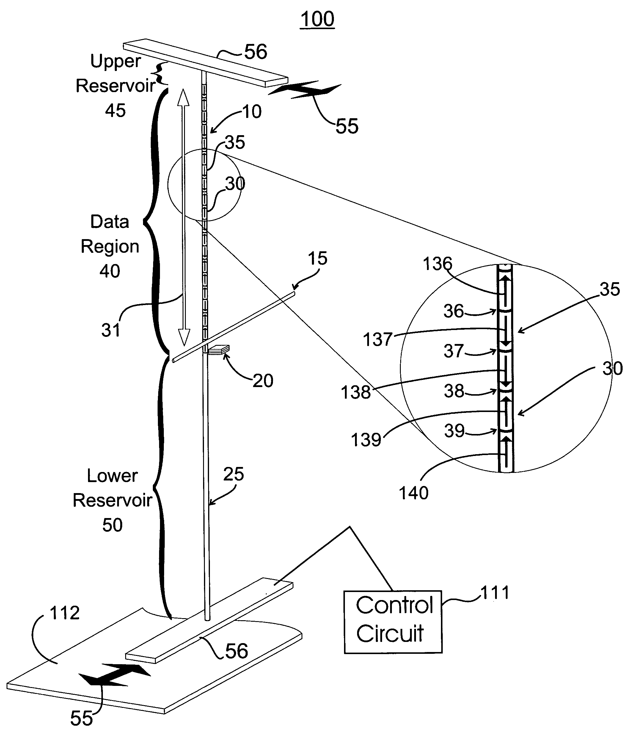
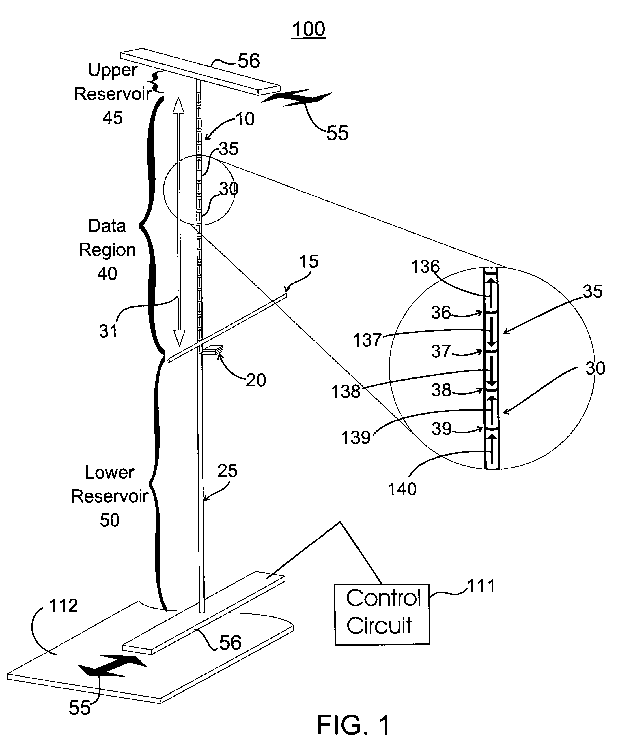
[0015]The reading element comprises a pinned layer with a fixed magnetic moment and a free (sense) layer with a magnetic moment that can be changed by application of an external magnetic field such as the fringing field from a domain wall, wherein the pinned layer and the sense layer are separated by a thin tunnel barrier so forming a magnetic tunnel junction (MTJ). The resistance of the MTJ varies according to the relative orientation of the magnetic moments of the sense and pinned layers so that the orientation of the sense layer magnetic moment will cause the resistance of the MTJ to be varied. It may be advantageous to form the MTJ from ferromagnetic electrodes and tunnel barrier materials that give rise to high TMR values, for example, MgO tunnel barriers and ferromagnetic electrodes formed from crystalline or amorphous alloys of Co and Fe.
[0019]In one embodiment, the magnetic moment of the free (sense) layer is biased in a direction that is perpendicular to that of the magnetic moment of the pinned layer. Application of the fringing field to the reading element causes the magnetic moment of the free (sense) layer to rotate up to 90° and align itself either more closely with the direction of the magnetic moment of the pinned layer, or to align itself more closely in the opposite direction of the magnetic moment of the pinned layer. This embodiment allows a reading element more sensitivity to the fringing fields of the domains, providing reading of data in the magnetic shift register with lower magnitude fringing fields or for faster operation.
[0021]By contrast, the magnetic shift register can be built at low cost per bit in much smaller sizes, thereby allowing the magnetic shift register to be used for a wide range of applications where the data storage capacity required is much lower than that of a magnetic hard disk drive. Thus the magnetic shift register can be used for various electronic devices including by way of example, but not limited to: digital cameras, personal digital assistants, security devices, memory sticks, removable storage devices, and so forth.

Problems solved by technology

However, disk drives are inherently unreliable.
Devices with moving parts tend to wear out and fail.
Solid-state random access memories currently store data on the order of 1 GB (gigabyte) per device, and are relatively expensive, per storage unit, compared to a disk drive.
In addition, flash memory cells can begin to lose data after less than a million write cycles.
While this may be adequate for some applications, flash memory cells may begin to fail rapidly if used constantly to write new data, such as in the main memory of a computer.
Further, the access time for flash memory is much too long for computer applications.
However, commercially available memory capacities are currently low, on the order of 1 MB (megabyte).
In addition, memory storage in a FRAM relies on physically moving atoms, leading to eventual degradation of the medium and failure of the memory.
However, the size of these memories is still small, on the order of 4 MB currently.
In addition, OUM relies on physically changing a material repeatedly to and from crystalline and amorphous states, likely causing the material to eventually degrade and fail.
However, currently available MRAM can only store up to 4 Mb (megabits), much less than needed for most memory applications.
In addition, each MRAM memory cell stores only one bit of data, thereby limiting the maximum possible memory capacity of such devices.

Method used


Image

  • System and method for transferring data to and from a magnetic shift register with a shiftable data column
  • System and method for transferring data to and from a magnetic shift register with a shiftable data column
  • System and method for transferring data to and from a magnetic shift register with a shiftable data column

Examples


Embodiment Construction

[0041]The following definitions and explanations provide background information pertaining to the technical field of the present invention, and are intended to facilitate the understanding of the present invention without limiting its scope:

[0042]Homogeneous magnetic material means a contiguous volume of magnetic material, which may have a complex shape, which nominally has the same or similar magnetic properties, such as magnetization, magnetic anisotropy, magnetic exchange and magnetic damping, independent of the position within the volume. At the surfaces surrounding such material, these properties may differ from the properties within the interior of the volume because of differences in strain or stress, compositional gradients, reaction with the surrounding material, etc.

[0043]Inhomogeneous magnetic material means a contiguous volume of magnetic material, which may have a complex shape, whose magnetic properties, such as magnetization, magnetic anisotropy, magnetic exchange and...


PUM


Abstract

A magnetic shift register utilizes a data column comprising a thin wire of magnetic material. A writing element selectively changes the direction of the magnetic moment in the magnetic domains to write the data to the data column. Associated with each domain wall are large magnetic fringing fields concentrated in a very small space. These magnetic fringing fields write to and read from the magnetic shift register. When the domain wall is moved close to another magnetic material, the fringing fields change the direction of the magnetic moment in the magnetic material, effectively “writing” to the magnetic material. A reading element similar to a tunneling junction comprises a free layer and a pinned layer of magnetic material. Fringing fields change the direction of the magnetic moment in the free layer with respect to the pinned layer, changing electrical resistance of the reading element and “reading” data stored in the magnetic shift register.

Description

CROSS-REFERENCE TO RELATED APPLICATIONS[0001]The present application is related to co-pending U.S. patent applications Ser. No. 10 / 458,554, titled “Shiftable Magnetic Shift Register and Method of Using the Same,” and Ser. No. 10 / 458,147, titled “System and Method for Writing to a Magnetic Shift Register,” both of which were filed on Jun. 10, 2003, and are incorporated herein by reference in their entirety.FIELD OF THE INVENTION[0002]The present invention generally relates to memory storage systems, and particularly to a memory storage system that uses the magnetization of magnetic domains, such as magnetic domain walls to store data. Specifically, the present invention relates to a magnetic shift register comprised of a data column, and a writing element and a reading element for data stored in the data column.BACKGROUND OF THE INVENTION[0003]The two most common conventional non-volatile data storage devices are disk drives and solid-state random access memories (RAM). Disk drives a...

Claims


Application Information

Patent Timeline
Patent Type & Authority Patents(United States)
IPC IPC(8): G11C7/00
CPCG11C11/14G11C19/08G11C19/0808
Inventor PARKIN, STUART S. P.
Owner GLOBALFOUNDRIES U S INC
Why Eureka
Try Eureka