Optical member for biological information measurement, biological information calculation apparatus, biological information calculation method, computer-executable program, and recording medium

a biological information and calculation apparatus technology, applied in the field of optical members for biological information measurement, can solve the problems of difficult to make lips adhere to the atr prism, difficult to accurately measure biological information, and disturbance light may cause adverse effects of biological information measurement, etc., to achieve the effect of suppressing the adverse effect of biological information measuremen

Active Publication Date: 2007-06-26
PANASONIC CORP
View PDF11 Cites 98 Cited by
  • Summary
  • Abstract
  • Description
  • Claims
  • Application Information

AI Technical Summary

Benefits of technology

[0067]The present invention has an advantage that it is possible to suppress the adverse effect to biological information measurement by disturbance light.

Problems solved by technology

Nevertheless, also in the first to third conventional art, light from other than a light source for measurement such as sunlight and light from illumination may constitute disturbance light in many cases.
Thereby, the above-mentioned conventional art has a subject that an adverse effect to biological information measurement by disturbance light may arise.
Therefore, it is hard to make lips adhere to the ATR prism.
For this reason, in the first and second conventional art, the accurate measurement of biological information may become hard.
Nevertheless, since the adhesion of the living body tissue and living body tissue measuring section is hard, when the adhesion of the living body tissue and living body tissue measuring section is insufficient, optical path length may vary, and the accurate measurement of biological information may become hard.

Method used


Image

  • Optical member for biological information measurement, biological information calculation apparatus, biological information calculation method, computer-executable program, and recording medium
  • Optical member for biological information measurement, biological information calculation apparatus, biological information calculation method, computer-executable program, and recording medium
  • Optical member for biological information measurement, biological information calculation apparatus, biological information calculation method, computer-executable program, and recording medium

Examples


embodiment 1

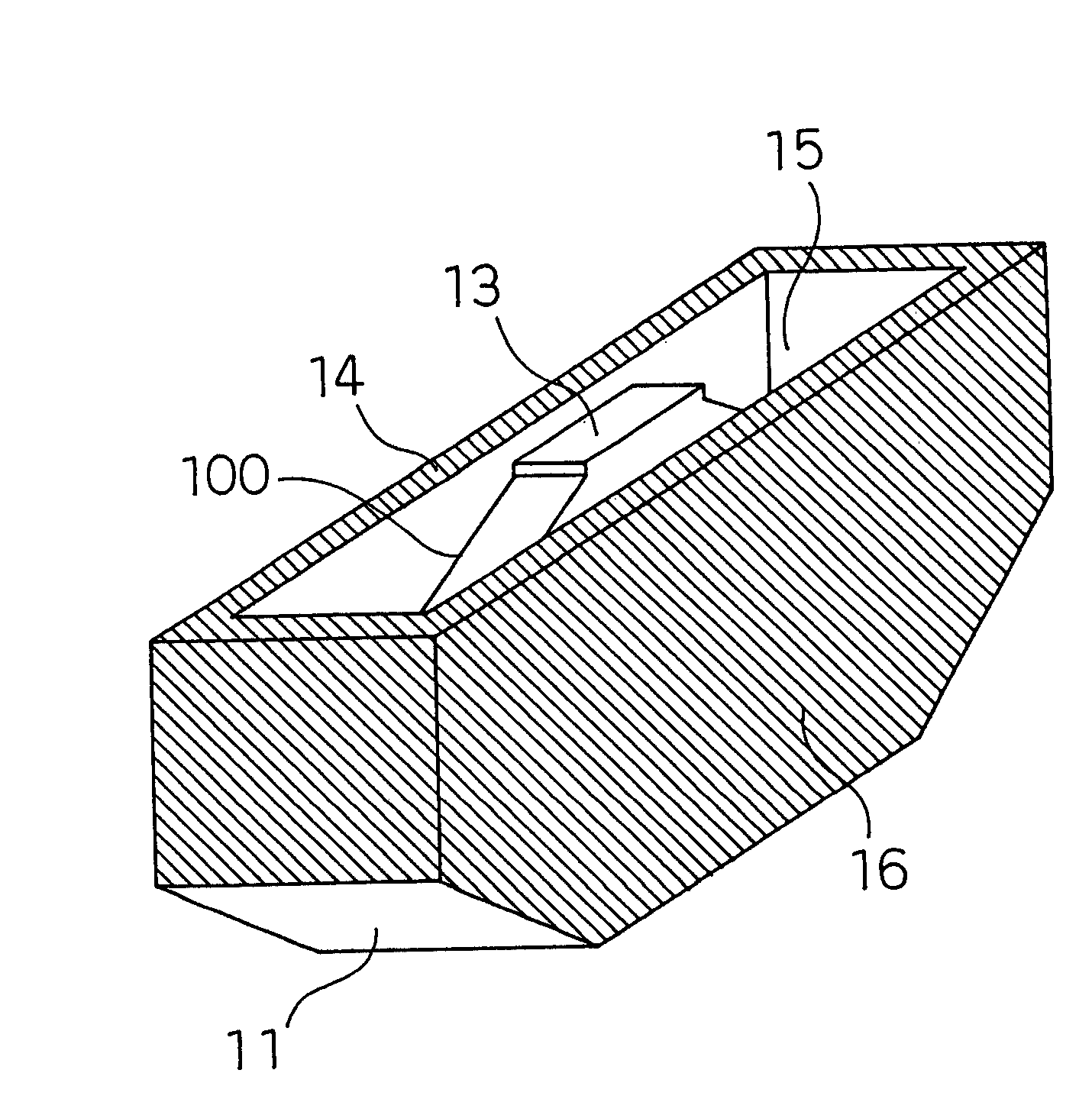
[0099]First, the configuration of an optical member for biological information measurement according to this embodiment will be described, mainly referring to FIGS. 1(a) to 1(c).

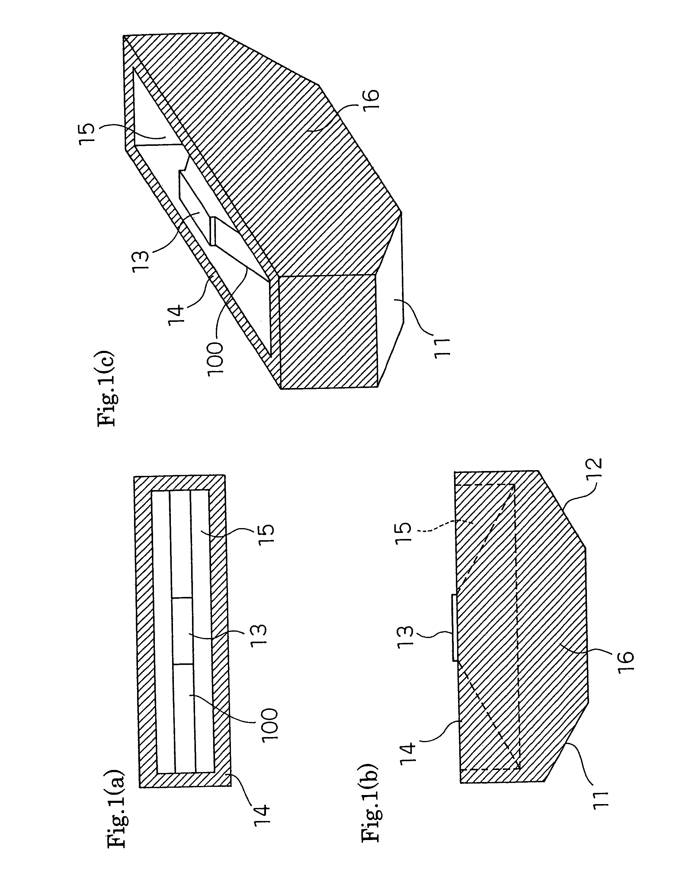
[0100]Here, FIG. 1(a) is a top view of the optical member for biological information measurement according to a first embodiment of the present invention, FIG. 1(b) is a side view of the optical member for biological information measurement of the first embodiment of the present invention, and FIG. 1(c) is a perspective view of the optical member for biological information measurement according to the first embodiment of the present invention.

[0101]As shown in FIG. 1(b), the optical member for biological information measurement according to this embodiment is constituted of a light incident surface 11, a light emitting surface 12, a living body tissue measuring section 13, a prism cover 14, and a living body tissue containing section 15.

[0102]That is, the optical member for biological information measurement...

embodiment 2

[0127]First, the configuration of an optical member for biological information measurement according to this embodiment will be described, mainly referring to FIGS. 3(a) to 3(c).

[0128]FIG. 3(a) is a perspective view of the optical member for biological information measurement before operation according to a second embodiment of the present invention, FIG. 3(b) is a perspective view of the optical member for biological information measurement after the operation, that is, in a state that a living body tissue is contacted to a living body tissue measuring section 313, according to the second embodiment of the present invention, and FIG. 3(c) is a sectional view, taken on line A-A′, of the optical member for biological information measurement before the operation according to the second embodiment of the present invention.

[0129]Although the configuration of the optical member for biological information measurement according to this embodiment is similar to the configuration of the opti...

embodiment 3

[0143]First, the configuration of an optical member for biological information measurement according to this embodiment will be described, mainly referring to FIG. 4.

[0144]Here, FIG. 4 is a bird's eye view of the optical member for biological information measurement according to the third embodiment of the present invention.

[0145]Although the configuration of the optical member for biological information measurement according to this embodiment is similar to the configuration of the optical member for biological information measurement according to the second embodiment mentioned above, vacuum ports 441 which penetrate a prism 400 and a bottom face section of a prism cover 414 are provided.

[0146]Of course, round windows are provided also in the living body tissue containing section cover 431 in positions of overlapping with the vacuum ports 441.

[0147]Therefore, a pump 499 can decompress the interior of a living body tissue containing section 415 by performing evacuation through such...


PUM


Abstract

An optical member for biological information measurement has a prism, which has a light incident surface being injected with emitted light, a living body tissue measuring section which a living body tissue contacts, and a light emitting surface which emits the light reflected by the living body tissue measuring section which the living body tissue contacts, or the light which has passed the living body tissue through the living body tissue measuring section which the living body tissue has contacted. A prism cover is provided so as to expose the living body tissue measuring section and to surround all or a part of the outer circumferential portion of the prism.

Description

BACKGROUND OF THE INVENTION[0001]1. Field of the Invention[0002]The present invention relates to an optical member for biological information measurement, a biological information calculation apparatus, a biological information calculation method, a computer-executable program, and a recording medium for calculating noninvasively glucose, cholesterol, urea, triglyceride, protein, and the like in body fluid by measuring a living body tissue optically.[0003]2. Related Art of the Invention[0004]A conventional optical measuring instrument for measuring a specific component in a living body or a solution will be described.[0005]There exists an optical measuring instrument for measuring a blood glucose level with making upper and lower lips adhere to a transparent attenuated total reflection element having a pair of reflecting surfaces facing each other in parallel (hereafter, referred to as an ATR prism) (e.g., refer to Japanese Patent Laid-Open No. 97-113439). It is assumed that this co...

Claims


Application Information

Patent Timeline
Patent Type & Authority Patents(United States)
IPC IPC(8): A61B5/00
CPCA61B5/14532A61B5/1455A61B5/682A61B5/6834G01N21/01G01N21/552G01N21/35G01N2201/021G01N21/359
Inventor SHIOI, MASAHIKOUCHIDA, SHINJI
Owner PANASONIC CORP
Why Eureka
Try Eureka