Humidifier for breathable gas apparatus

a gas apparatus and humidifier technology, applied in the field of humidifiers, can solve the problems of inability to easily vary the amount of humidification of gas, the expense of heating elements and associated thermostatic temperature control equipment,

Inactive Publication Date: 2007-07-03
RESMED LTD
View PDF36 Cites 43 Cited by
  • Summary
  • Abstract
  • Description
  • Claims
  • Application Information

AI Technical Summary

Benefits of technology

[0043]an adjustable flow divider adapted to divide the interior of the body above the maximum water level into a relatively dry gas region and a relatively wet gas region, wherein the position of the divider is variable so as to vary the relative proportion of the gas flowing from the inlet to the outlet that passes through the relatively dry and relatively wet gas regions-to thereby vary the amount of humidification thereof.

Problems solved by technology

A disadvantage of known active humidifiers is the expense of the heating elements and associated thermostatic temperature control equipment.
A disadvantage of known passive humidifiers is an inability to easily vary the amount of humidification of the gas.

Method used


Image

  • Humidifier for breathable gas apparatus
  • Humidifier for breathable gas apparatus
  • Humidifier for breathable gas apparatus

Examples


first embodiment

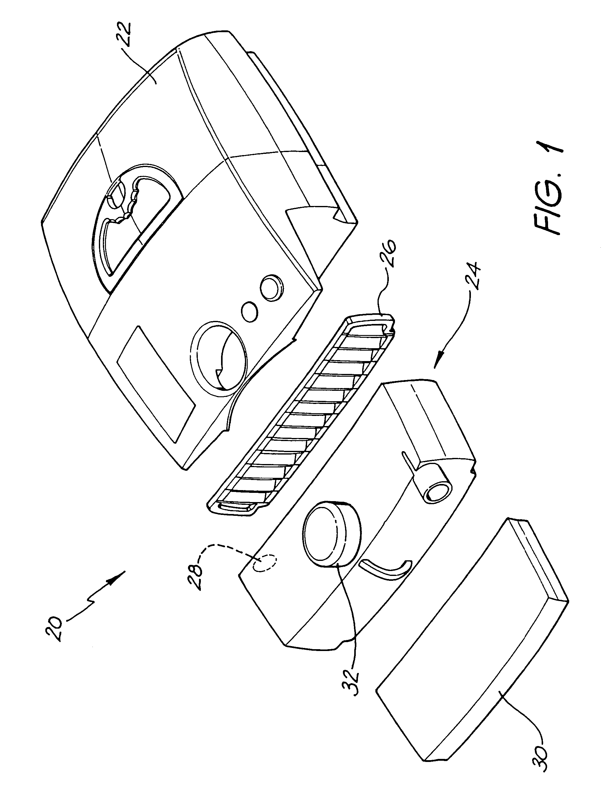
[0063]FIG. 1 is an exploded view of a breathable gas supply apparatus 20 which comprises a flow generator 22, a humidifier 24 according to the invention, an anti-bacterial filter 26 and a heating element 30. The filter 26 is operatively positioned between the outlet of the flow generator 22 (not shown) and the inlet 28 of the humidifier 24. In another embodiment (not shown), the filter is operatively positioned between the outlet of the humidifier and the patient. In the latter, the filter reduces the transfer of bacteria from the patient to the humidifier, and vice-versa.

[0064]The humidifier 24 includes a control knob 32 which can be rotated in order to vary the amount of humidification of the gas flowing through the humidifier between a maximum and minimum amount. The components of the humidifier 24 which permit this adjustable humidification will be more completely described with reference to the embodiments of the invention shown in FIGS. 2 to 9, 11, 12, 13, 14, 15, 16 and 17.

[0...

second embodiment

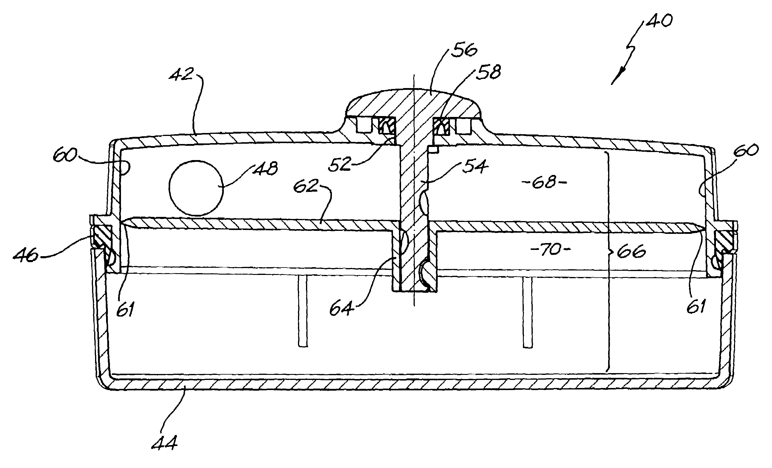
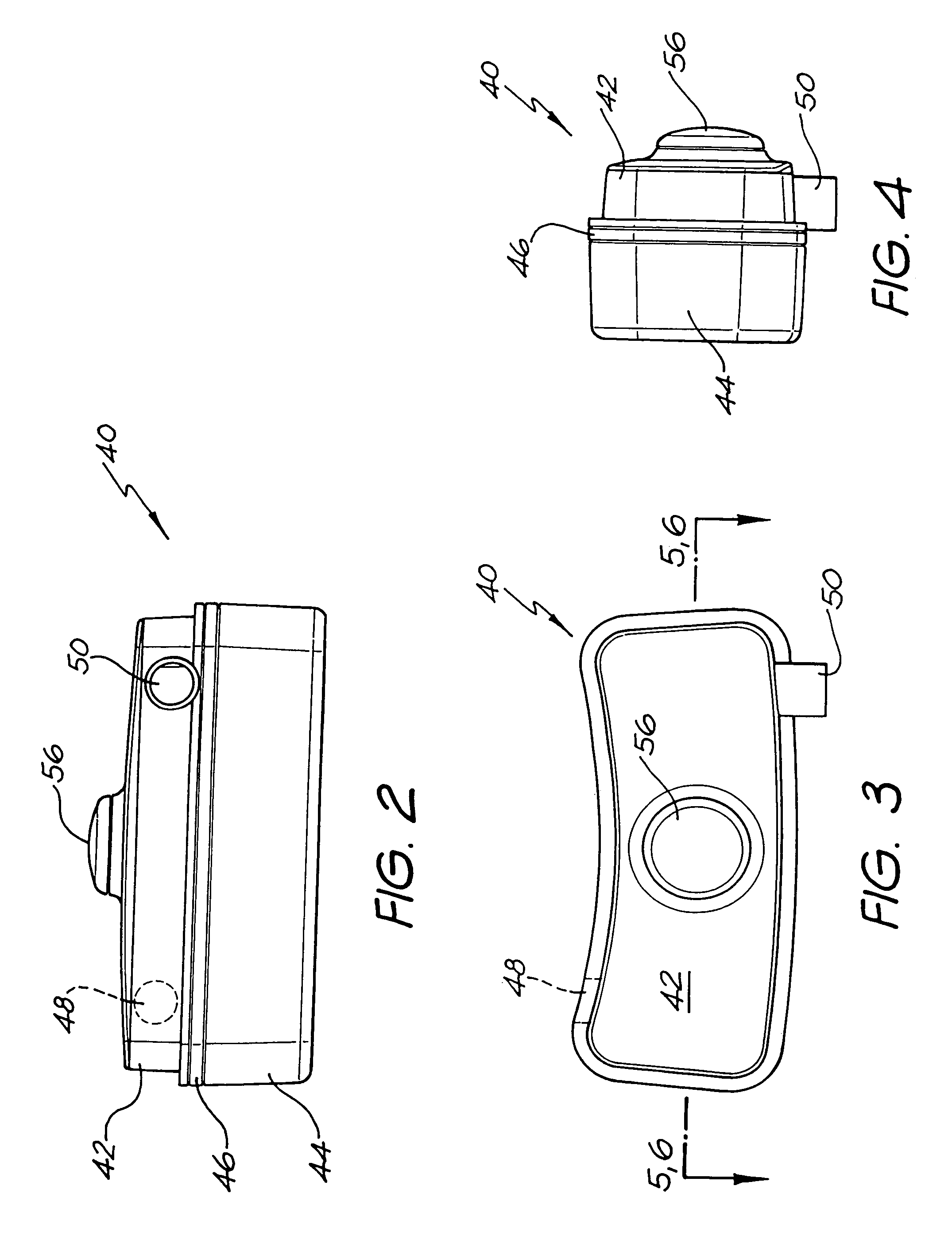
[0067]a humidifier 40 is shown in FIGS. 2 to 9. As best shown in FIGS. 2 to 4, the humidifier 40 includes a hollow body formed from an upper body portion 42 and a lower body portion 44. A fluid tight seal 46 is disposed between the upper and lower body portions 42 and 44.

[0068]The upper body portion 42 includes a gas inlet 48 and a gas outlet 50.

[0069]As best shown in FIG. 5, the upper body portion 42 also includes an opening 52 through which passes a threaded shaft 54. The shaft 54 depends from an external control knob 56.

[0070]A fluid tight seal 58 is provided around the shaft adjacent the knob 56 and the boss 52. The upper casing 42 includes substantially parallel internal side walls 60 which are adapted to provide a substantially fluid tight seal with the external edges 61 of a flow dividing plate 62. However, a fluid tight seal is not critical.

[0071]The plate 62 includes a central threaded boss 64 which threadably engages the shaft 54. Rotation of the knob 56 causes the boss 64...

sixth embodiment

[0086]FIG. 15 shows a humidifier 120 according to the invention and like reference numerals will again be used to denote like features to earlier embodiments. The humidifier 120 is similar to the humidifier 90 shown in FIG. 11 in that it has a water storage tank 92 mounted above the humidification interior 66. However, in this embodiment, the flow dividing plate 62 pivots at one end about axis 122, as indicated by arrow 123, between maximum and minimum humidification positions. The humidifier 120 also includes a plug 124 to allow filling of the water storage tank 92. The humidifier 120 is shown mounted above a heating element assembly 126 which comprises a heating element 128 within an outer casing 129.


PUM

PropertyMeasurementUnit
pHaaaaaaaaaa
volumeaaaaaaaaaa
lengthaaaaaaaaaa

Abstract

A humidifier for use with a breathable gas supply apparatus includes a hollow body adapted for partial filling with water to a predetermined maximum water level, a gas inlet to the body above the maximum water level and a gas outlet from the body above the maximum water level. The humidifier further includes a temperature heating element for heating the water and / or an adjustable flow divider adapted to divide the interior of the body above the maximum water level into a relatively dry gas region and a relatively wet gas region. The position of the divider is variable so as to vary the relative proportion of the gas flowing from the inlet to the outlet that passes through the relatively dry and relatively wet gas regions to thereby vary the amount of humidification thereof.

Description

CROSS REFERENCE TO RELATED APPLICATIONS[0001]This application is a divisional of U.S. application Ser. No. 10 / 387,534, now U.S. Pat. No. 6,772,999, filed Mar. 14, 2003, which is a continuation of U.S. application Ser. No. 09 / 689,775, now U.S. Pat. No. 6,554,260, filed Oct. 13, 2000, which claims priority to Australian Application No. PQ3390 filed Oct. 13, 1999, the contents of which are incorporated herein by reference in their entireties.FIELD OF THE INVENTION[0002]The present invention relates to a humidifier.[0003]The invention has been developed primarily for use with a breathable gas supply apparatus in Continuous Positive Airway Pressure (CPAP) treatment of, for example, Obstructive Sleep Apnea (OSA) and other ventilatory assistance treatments such as Non Invasive Positive Pressure Ventilation (NIPPV) and will be described hereinafter with reference to these applications. However, it will be appreciated that the invention is not limited to these particular fields of use and al...

Claims


Application Information

Patent Timeline
Patent Type & Authority Patents(United States)
IPC IPC(8): B01F3/04A61M16/00A61M16/10A61M16/16
CPCA61M16/1055A61M16/1075A61M16/16A61M16/109A61M16/0057A61M2205/3386A61M2205/3393A61M16/021
Inventor LIPSCOMBE, MATTHEWJONES, RICHARD L.
Owner RESMED LTD
Why Eureka
Try Eureka