Method and apparatus for a projection system

Inactive Publication Date: 2007-07-03
STAHL ALEXANDER W
View PDF8 Cites 37 Cited by
  • Summary
  • Abstract
  • Description
  • Claims
  • Application Information

AI Technical Summary

Benefits of technology

[0005]The present invention provides solutions for at least some of the drawbacks discussed above. Specifically, some embodiments of the present invention provide an improved light projection system. Although not limited to the following, such a system is particularly useful in image projection systems. One embodiment of the new approach being proposed in this patent eliminates the need for high power xenon arc lamps as well as by design eliminates the physical limitation of the optical invariant. The proposed embodiment will use all the available light directed toward the image plane with minor losses compared to the xenon / reflector approach. Embodiments of the present invention allow for the desired brightness of white light, the present invention provides a novel solution. At least some of these and other objectives described herein will be met by some embodiments of the present invention.
[0007]One embodiment of the current approach uses several unique optical elements to maximize a bright, uniform cinema screen. In this embodiment, the high power xenon arc lamp is replaced with banks of high brightness, low power light emitting diodes. The light from the diodes is captured using a custom designed optical collimator, which in one embodiment, provides an output of no more than about 3 degrees and outputs 95% of the light coming from a light sources such as an LED lamp source. It should be understood that in other embodiments, the collimator may provide no more than 4, 3.5, 3, 2.5, or 2 degrees. It should be understood that in other embodiments, the collimator may provide outputs 90%, 91%, 92%, 93%, 94%, 95%, 96%, 97%, 98%, 99%, and / or 100% of light coming from light sources. Once collimated, the light is easily controlled by other optical components, such as but not limited to fresnel-lens, first surface mirrors, and micro-lens all of which contribute to maintaining a uniform bright source directed to the image plane. In one embodiment, the image plane itself is a large liquid crystal panel with a minimum diagonal of about 9 inches. It is the size of this panel that allows the system to overcome the optical invariant problem of other manufactures. To increase the overall brightness of the system the light passes through a set of unique wire grid polarizers that orient the light to one polarizing component only. Other simple fresnel lens direct the image to the projection lens which then transfers it to the cinema screen. The brightness of the screen is a function of the number of LEDs that we employ at the start of the optical process.
[0018]In some embodiments of the present invention, the system comprises any digital projector that uses projection lenses that are liquid filled for low manufacturing cost and very high performance.

Problems solved by technology

Because of the size of the arc gap, significant amounts of light were lost and only a very small percentage was usable for the projected image.
Unfortunately they cannot over come the optical invariant and like the original Edison metallic arc and lose a significant portion of the usable light.
Frequently, these systems are unable to provide a uniform, bright, homogenized output.
Projection systems using LCD image panels are at a further disadvantage since the LCD panel polarizes light and in do so, rejects 50% of the light that are at the wrong polarization.

Method used


Image

  • Method and apparatus for a projection system
  • Method and apparatus for a projection system
  • Method and apparatus for a projection system

Examples


first embodiment

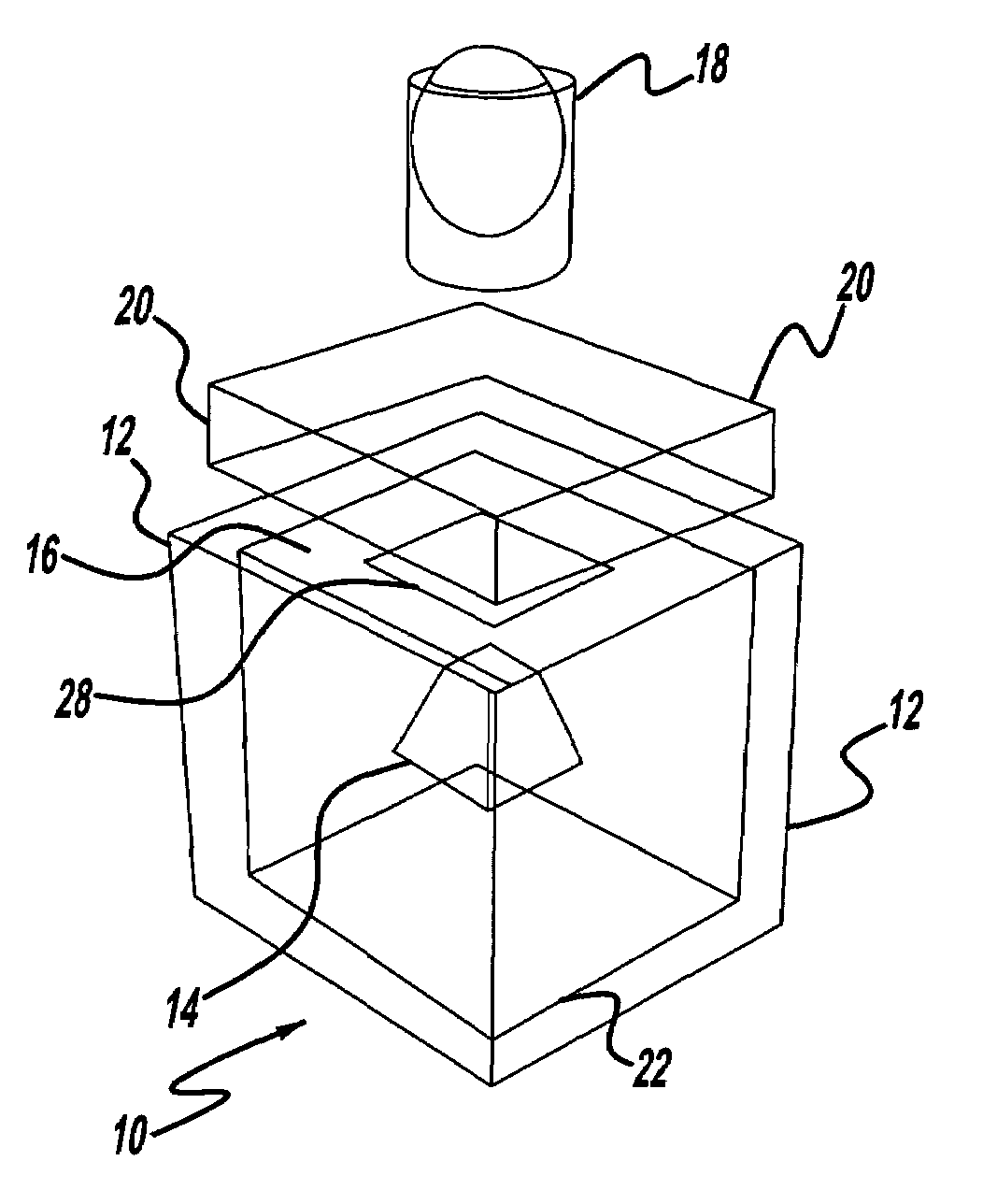
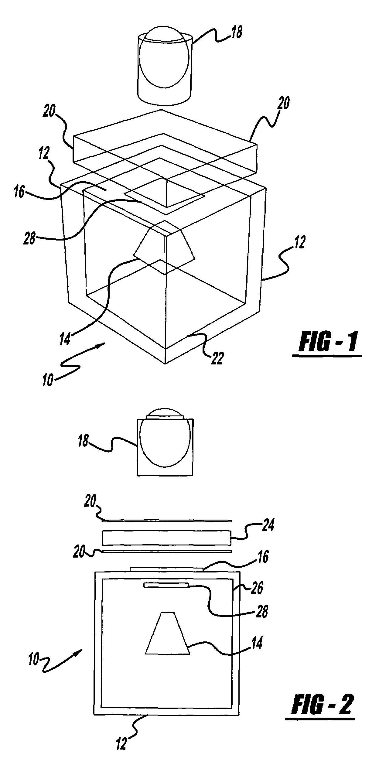
[0032]With respect to the first embodiment shown in FIGS. 1 through 3, a projection system 10 is generally illustrated. It is understood that a cube has six sides. Referring now to FIG. 1, it is seen that embodiments of the present invention may use the form of a cube with the exception of one side. The present embodiment optionally uses five sides of a cube. Each of the sides, or on the five sides there's mounted, attached or secured in any fashion, light sources 12. The light source may be but is not limited to mercury, high pressure xenon, HID, LED, florescent etc., sources. It should be understood that, in some embodiments of the present invention, any means to produce light will be satisfactory. In the present embodiment, all of these light sources 12 will be mounted etc., on the inside surfaces so that they face each other or they all are directed to the virtual center point inside the cube. They can be directed to the center point of the cube by the method or means of an opti...

second embodiment

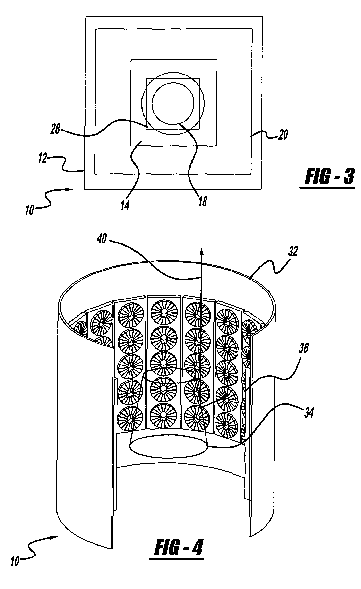
[0036]FIGS. 4 through 6 illustrate the projection system of the present invention having a conical configuration. According to this arrangement, a projection system, generally illustrated as 30, includes an LED cylinder housing 32, a reflective cone 34, and an LED array 36. (Note that FIGS. 4 and 6 are illustrated with a section taken out for ease of visualization.) The various light sources which in this embodiment is shown as an LED array 36 may direct light at the reflective cone 34 to direct light in the direction indicated by arrow 40. It should be understood that the system 30 may be but is not limited to combined for use with various elements of FIG. 2 by, in one non-limiting example, replacing system 10 with system 30.

[0037]Referring now to FIGS. 7A and 7B as a nonlimiting example, in one embodiment, the light source 12 may be but is not limited to a single LED assembly. This assembly may be but is not limited to the following components—LED light source 50, heat sink 52, an...


PUM


Abstract

Methods and apparatus for providing a projection system. In one embodiment, the system provides plurality of light sources collimating light using a parabolic concentrator. The system may direct light from a plurality of light sources towards a light collector which directs light towards a fresnel lens which directs light to a polarizing recombiner. The system may also usiethe recombiner to allow light having a first polarization to pass. The recombiner to convert light of a second polarization to light having the first polarization and letting converted light pass to an LCD image panel. In another embodiment, a projection system having a light source capable of achieving a bright, homogenized output is disclosed. The present invention provides such a projection system through at least two embodiments. The first projection system may use a cubic projection system. The second may use a conical projection system.

Description

CROSS REFERENCE TO RELATED APPLICATION[0001]This application claims the benefit of priority from co-pending U.S. Provisional Patent Application Ser. No. 60 / 420,249 filed Oct. 23, 2002. This application is fully incorporated herein by reference for all purposes.BACKGROUND OF THE INVENTION[0002]The present invention relates to projection systems. More particularly, some embodiments of the present invention relate to a projection system having uniform, bright, homogenized output.[0003]Projection systems have been known for some time. Cinema projectors until recently have all been based on analog technology. Historically, Thomas Edison invented a device called the “kinescope”, which passed a light through a transparent medium. This device used an electric arc lamp to produce the light required for projection. Because of the size of the arc gap, significant amounts of light were lost and only a very small percentage was usable for the projected image. Modern advancements were mostly mech...

Claims


Application Information

Patent Timeline
IPC IPC(8): F21V7/00G03B21/00G03B21/14
CPCG03B21/00G03B21/14G03B21/208G03B21/142G03B21/005
Inventor STAHL, THOMAS D.
Owner STAHL ALEXANDER W
Why Eureka
Try Eureka