Very fast doped LaBr3 scintillators and time-of-flight PET

Active Publication Date: 2005-05-19
RADIATION MONITORING DEVICES
View PDF31 Cites 67 Cited by
  • Summary
  • Abstract
  • Description
  • Claims
  • Application Information

AI Technical Summary

Benefits of technology

[0035] If there is no Time-of-Flight (TOF) information, equal probability is assigned to each point on the line. The reconstruction of the image then proceeds by one of the dozens of algorithms known in the art. If TOF information is available, then the probability of origin of the event along the line can be represented as a Gaussian or similar distribution of width equal to the TOF FWHM, centered on the most probable point. Similar reconstruction algorithms, modified to take advantage of the TOF information can be used for reconstruction, and these modifications are also well known in the art.
[0036] In a further embodiment the present invention comprises an X-ray compute

Problems solved by technology

Nevertheless, a common aspect of all image formation or reconstruction algorithms is that the noise increases in the process of deciding where along the detected line the annihilation event is likely to have occurred.
While any improvement in time resolution aids in accidentals reduction, until the time resolution drops substantially below about 1 ns, greater time resolution will not help in localization of an annihilation event within a target of about 30 cm—the more common presentation in human-PET scanning.
With that limitation, an improvement in localization from 4 nanosecondss (4 feet) to 1 nanosecond (1 foot) offers no improvement to image quality.
Hitherto no true time-of-flight PET device has been enabled

Method used


Image

  • Very fast doped LaBr3 scintillators and time-of-flight PET
  • Very fast doped LaBr3 scintillators and time-of-flight PET
  • Very fast doped LaBr3 scintillators and time-of-flight PET

Examples


example 1

LaBr3 Crystals, Bridgman Method

[0081] In making crystals, ultra-dry forms of LaBr3 and CeBr3 were used with 99.99% purity. A two zone Bridgman furnace was used with temperature in the hotter zone above the melting point LaBr3 (783° C.) and that of the cooler zone below the melting point. The amount of CeBr3 in the feed material was adjusted to produce LaBr3 samples with varying Ce3+ concentration. Most growth runs were performed with 0.5% cerium concentration, although some runs were also performed with other Ce3+ concentrations (e.g., 0.2%, 0.5%, 1.3%, 5%, 10%, 20% and 30%). LaBr3 crystals with a size of up to ˜2.3 cm3 were grown. These crystals were cut from the solid ingots and polished using non-aqueous slurries (due to hygroscopic nature of LaBr3) prepared by mixing mineral oil with Al2O3 grit. The crystals were then packaged to prevent long exposure to moisture. This involved encapsulating the crystal in an epoxy (e.g., Epoxy STYCAST #1266 Value23LV Titanium Oxide and EPO-TE...

example 2

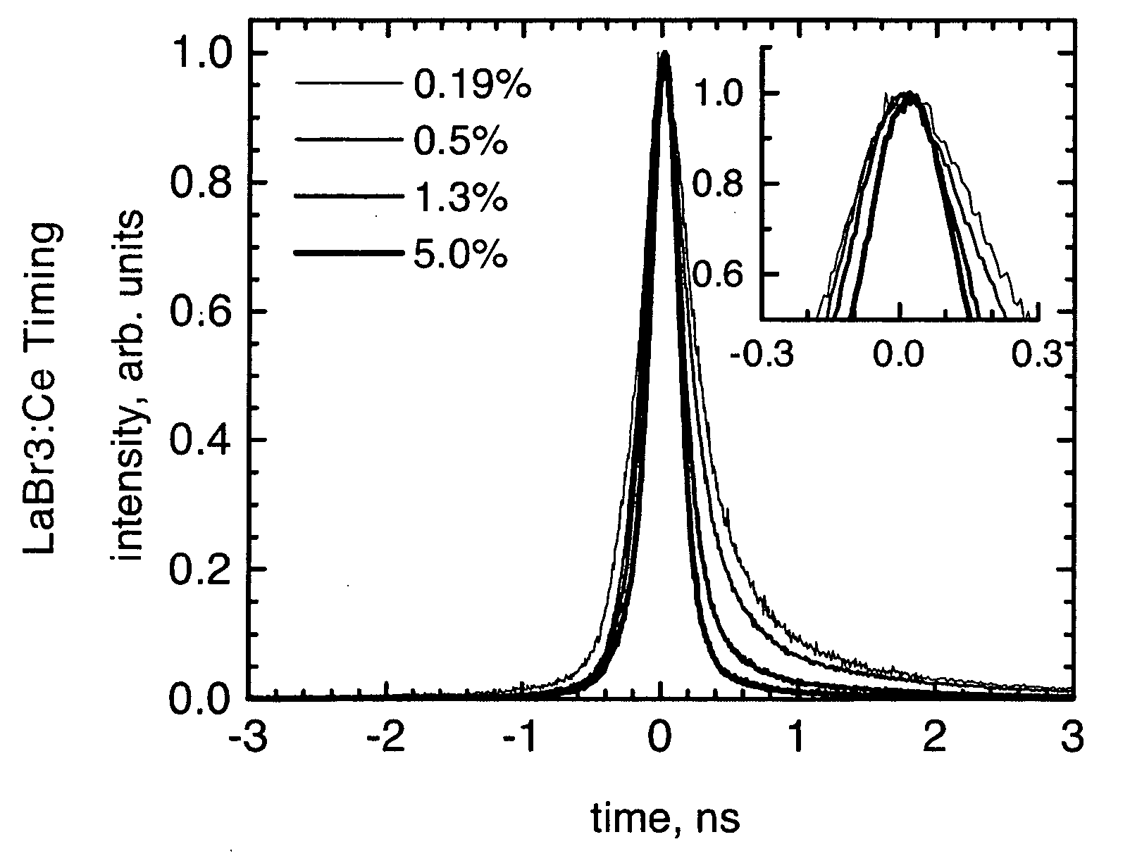
LaBr3:Ce, Scintillation Properties

[0082] Characterization of the scintillation properties of LaBr3 crystals grown by the Bridgman process involved measurement of the light output, the emission spectrum, and the fluorescent decay time of the crystals. Variation of these scintillation properties with Ce3+ concentration was analyzed. Energy and timing resolution of LaBr3:Ce crystals were also measured.

Light Output and Energy Resolution

[0083] The light output of LaBr3:Ce crystals was measured by comparing their response and the response of a calibrated BGO scintillator to the same isotope (662 keV γ-rays, 137Cs source, see FIG. 9). These measurements involved optical coupling of a LaBr3:Ce sample to a photomultiplier tube (with multi-alkali S-20 photocathode), irradiating the scintillator with 662 keV photons and recording the resulting pulse height spectrum. In order to maximize light collection, LaBr3:Ce crystals were wrapped in reflective, white Teflon tape on all faces (except ...


PUM


Abstract

The present invention concerns very fast scintillator materials capable of resolving the position of an annihilation event within a portion of a human body cross-section. In one embodiment, the scintillator material comprises LaBr3 doped with cerium. Particular attention is drawn to LaBr3 doped with a quantity of Ce that is chosen for improving the timing properties, in particular the rise time and resultant timing resolution of the scintillator, and locational capabilities of the scintillator.

Description

CROSS-REFERENCES TO RELATED APPLICATIONS [0001] This application claims the benefit of U.S. Provisional Patent Application No. 60 / 505,636, entitled “Very Fast Doped LaBr3 Scintillators and Time-of-Flight PET,” filed Sep. 24, 2003, the complete disclosure of which is incorporated herein by reference in its entirety.STATEMENT AS TO RIGHTS TO INVENTIONS MADE UNDER FEDERALLY SPONSORED RESEARCH OR DEVELOPMENT [0002] Aspects of this research was conducted with funding provided by the Department of Energy and the National Institute of Health. Contract No. DE-AC03-76SF00098 and Grant Nos. R01-CA6791 1 and P01-HL25840, respectively. The United States Government may have certain rights in the application.BACKGROUND OF THE INVENTION [0003] The present invention relates generally to scintillators. More specifically, the present invention provides lanthanum bromide (LaBr3) scintillators for use with medical imaging scanner systems, such as time-of-flight PET scanner systems. [0004] One form of m...

Claims


Application Information

Patent Timeline
IPC IPC(8): C09K11/77G01T1/164G01T1/172
CPCC09K11/7772C30B11/00C30B29/12G01T1/172
Inventor SHAH, KANAI S.
Owner RADIATION MONITORING DEVICES
Why Eureka
Try Eureka