Glass wrapping layer scintillating fiber and preparation method thereof
A technology for scintillation optical fiber and glass cladding, which is applied in the direction of cladding optical fiber, glass manufacturing equipment, manufacturing tools, etc., which can solve the problems of reduced light output, excessive fiber diameter, and large Si penetration, etc., to achieve high light output and increase Light output, fast decay effect
- Summary
- Abstract
- Description
- Claims
- Application Information
AI Technical Summary
Problems solved by technology
Method used
Image
Examples
Embodiment 1
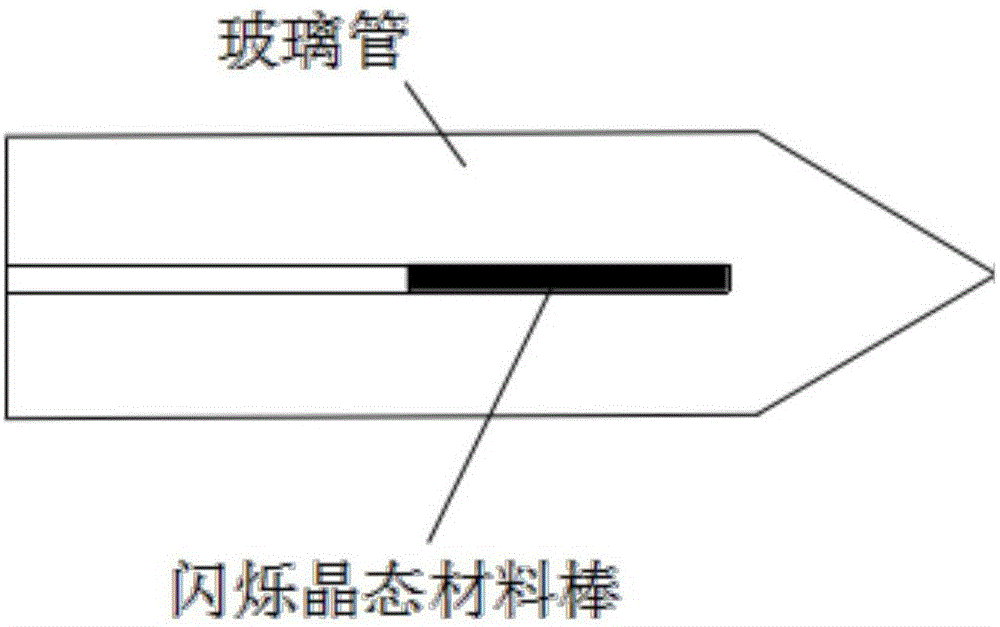
[0017] Embodiment 1: (m=0, n=0, x=0.2, y=0.3, z=0.5), A is Gd, RE is Ce 3+ , cladding glass material composition 0.2SiO 2 0.3Y 2 o 3 0.5Al 2 o 3 , the core has a garnet structure, and its component Ce 0.1 :Y 3 al 5 o 12 . Cylindrical ceramic rods were prepared by doping Ce ion-doped garnet structure crystalline material, and the inner diameter of the cladding glass tube matched the outer diameter of the crystalline material. One end of the glass tube is collected by the MCVD machine tool and drawn into a tapered shape to form an optical fiber preform (such as figure 1 shown), put the optical fiber preform into the graphite furnace drawing tower for drawing. The operation process is as follows: Insert one end of the conical seal into the graphite furnace, heat and draw. Put the drawn optical fiber in a muffle furnace for heat treatment and keep it warm for a period of time.
Embodiment 2
[0018] Embodiment 2: (m=1, n=1, x=0.4, y=0.225, z=0.375), A is Gd, RE is Pr 3+ , cladding glass material composition 0.4SiO 2 0.225Y 2 o 3 0.375Al 2 o 3 , the core has a garnet structure, and its component Pr 0.1 :Y 3 al 5 o 12 . Cylindrical rods are prepared by doping Pr ions into garnet crystals, and the inner diameter of the cladding glass tube matches the outer diameter of the crystalline material. One end of the glass tube is collected by the MCVD machine tool and drawn into a tapered shape to form an optical fiber preform (such as figure 1 shown), put the optical fiber preform into the graphite furnace drawing tower for drawing. The operation process is as follows: Insert one end of the tapered seal into the graphite furnace, heat, wire-draw. Put the drawn optical fiber in a muffle furnace for heat treatment and keep it warm for a period of time.
Embodiment 3
[0019] Embodiment 3: (m=2 / 3, n=3 / 5, x=0.4, y=0.225, z=0.375), A is Gd, and RE is Yb 3+ , cladding glass material composition 0.4SiO 2 0.225Y 2 o 3 0.375Al 2 o 3 , the core has a garnet structure, and its component Yb 0.1 :Gd 1 Y 2 Ga 2 al 3 o 12 . The Yb ion doped garnet structure crystalline material is prepared into a cylindrical rod, and the inner diameter of the cladding glass tube matches the outer diameter of the crystalline material. One end of the glass tube is collected by the MCVD machine tool and drawn into a tapered shape to form an optical fiber preform (such as figure 1 shown), put the optical fiber preform into the graphite furnace drawing tower for drawing. The operation process is as follows: Insert one end of the conical seal into the graphite furnace, heat and draw. Put the drawn optical fiber in a muffle furnace for heat treatment and keep it warm for a period of time.
[0020] The wavelength of fluorescence emitted by the scintillation optica...
PUM
 Abstract
Description
Claims
Application Information
 - R&D
- Intellectual Property
- Life Sciences
- Materials
- Tech Scout
- Unparalleled Data Quality
- Higher Quality Content
- 60% Fewer Hallucinations
Browse by: Latest US Patents, China's latest patents, Technical Efficacy Thesaurus, Application Domain, Technology Topic, Popular Technical Reports.
© 2025 PatSnap. All rights reserved.Legal|Privacy policy|Modern Slavery Act Transparency Statement|Sitemap|About US| Contact US: help@patsnap.com


