Metal ion emission device and process for producing the same, ion beam irradiation device, processing apparatus and analyzing apparatus provided with emission device

a technology of ion beam irradiation and emission device, which is applied in the manufacture of sparking plugs, instruments, electric discharge tubes/lamps, etc., can solve the problem of difficult to achieve a very minute ion emission area, and achieve the effect of minute area

Inactive Publication Date: 2007-07-03
CANON KK
View PDF4 Cites 8 Cited by
  • Summary
  • Abstract
  • Description
  • Claims
  • Application Information

AI Technical Summary

Problems solved by technology

Therefore, it is difficult to achieve a very minute ion emission area.

Method used


Image

  • Metal ion emission device and process for producing the same, ion beam irradiation device, processing apparatus and analyzing apparatus provided with emission device
  • Metal ion emission device and process for producing the same, ion beam irradiation device, processing apparatus and analyzing apparatus provided with emission device
  • Metal ion emission device and process for producing the same, ion beam irradiation device, processing apparatus and analyzing apparatus provided with emission device

Examples


example

[0024]The present invention will now be described with reference to the example. However, the present invention should not be limited to this example.

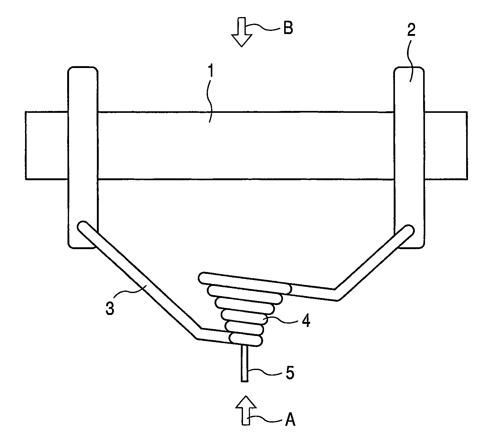
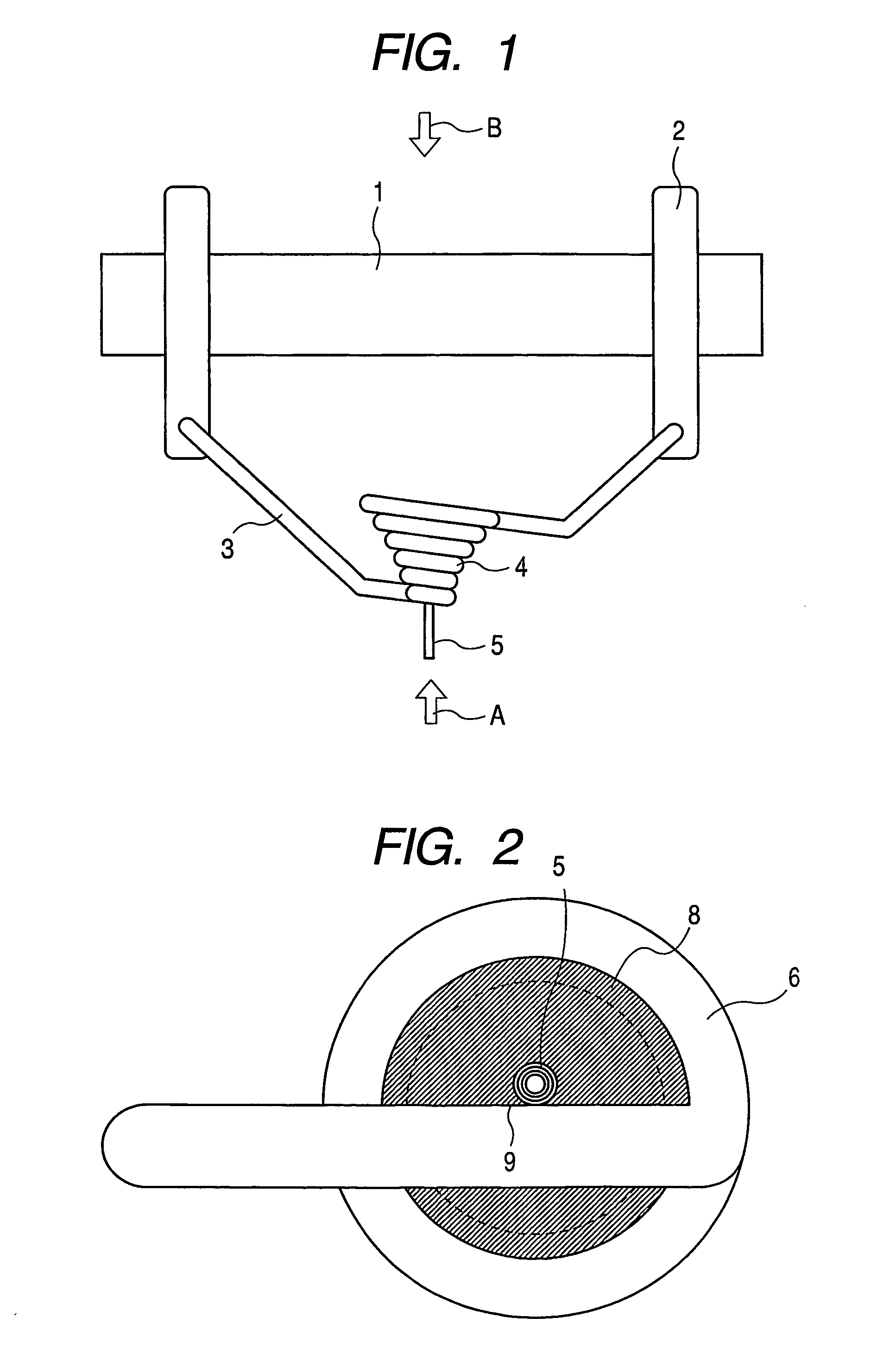
[0025]FIG. 1 shows a structure of a metal ion emission device in this example. FIG. 2 shows an enlarged schematic view of an apex of a reservoir in this device viewed in the direction of the arrow A in FIG. 1. In FIG. 1, the reference numeral 1 denotes an insulator, the reference numeral 2 denotes column electrodes penetrated into and secured to the insulator 1, the reference numeral 3 denotes a tungsten wire spot-welded to the column electrodes 2, the reference numeral 4 denotes the reservoir obtained by forming the tungsten wire 3 into a spiral, and the reference numeral 5 denotes a multi-walled carbon nanotube (MWCNT) with both ends opened. In FIG. 2, the reference numeral 6 denotes the apex of the reservoir, and the reference numeral 8 denotes hydrocarbon for joining the carbon nanotube to the reservoir.

[0026]First, one example of ...


PUM

PropertyMeasurementUnit
voltageaaaaaaaaaa
mass analysisaaaaaaaaaa
current densityaaaaaaaaaa

Abstract

A metal ion emission device for emitting a metal ion by applying voltage to a molten liquid metal includes a needle-like part having an internal opening in which the liquid metal can be moved. The needle-like part has a first opening for supplying the liquid metal to the opening and a second opening for emitting the liquid metal as a metal ion.

Description

TECHNICAL FIELD[0001]The present invention relates to a metal ion emission device for emitting a metal ion from a liquid metal, an ion beam irradiation device provided with the metal ion emission device, a processing apparatus and an analyzing apparatus provided with the ion beam irradiation device, and a process for producing the metal ion emission device. More particularly, the present invention relates to the metal ion emission device used for processing or film-forming in a minute region, mass analysis of a minute region or the like, and a process for producing the device.BACKGROUND ART[0002]When a liquid metal ion source (abbreviated to LMIS), in which a metal ion is emitted by applying an intense electric field to a molten liquid metal, is used, the ion can be emitted from a minute area, and a minute probe can be focused on a sample while maintaining a high current density. In recent years, LMIS thus characterized by high luminance and minuteness of a probe has become applied ...

Claims


Application Information

Patent Timeline
Patent Type & Authority Patents(United States)
IPC IPC(8): H01J27/00G01N23/225G21K1/00G21K5/04H01J9/02H01J27/22H01J27/26H01J37/08H01J37/252H01J37/317
CPCB82Y10/00H01J27/26H01J37/08H01J2237/0805
Inventor OHTSUKA, MITSURU
Owner CANON KK
Why Eureka
Try Eureka