Serially RC coupled quadrature oscillator

a quadrature oscillator, voltage control technology, applied in the direction of oscillator generator, logic circuit pulse generation, pulse technique, etc., can solve the problems of easy generation of noise, complex circuit design, and easy generation of phase noise, so as to reduce noise generation, reduce power consumption and scale-down of the circuit, the effect of reducing the number of transistors

Inactive Publication Date: 2007-07-03
SHARP KK
View PDF10 Cites 31 Cited by
  • Summary
  • Abstract
  • Description
  • Claims
  • Application Information

AI Technical Summary

Benefits of technology

[0022]The present invention was made in view of the above problems, and an object of the present invention is to provide an oscillator which realizes less noise and lower power consumption.
[0028]Here, as previously described, the present invention uses series-connected coupling resistor and coupling capacitor for the coupling between the transistors belonging to the first oscillator circuit and the transistors belonging to the second oscillator circuit. Therefore, the arrangement of the present invention reduces noise generation as compared with the conventional arrangement using a transistor coupling, a transformer coupling, or the like. Besides, the arrangement of the present invention reduces transistor counts, thus realizing lower power consumption and scale-down of a circuit.
[0032]According to the above arrangement, series-connected resistor and capacitor are used for the coupling between the transistors belonging to the first oscillator circuit and the transistors belonging to the second oscillator circuit. Therefore, the arrangement of the present invention reduces noise generation as compared with the conventional arrangement using a transistor coupling, a transformer coupling, or the like. Besides, the arrangement of the present invention reduces transistor counts, thus realizing lower power consumption and scale-down of a circuit.

Problems solved by technology

On this account, the power consumption of the oscillator increases, and the circuit (flip flop circuit) design becomes complex.
On this account, noise (phase noise, etc.) is easily generated, and the power consumption increases.
On this account, a circuit area increases, and the power consumption also increases.

Method used


Image

  • Serially RC coupled quadrature oscillator
  • Serially RC coupled quadrature oscillator
  • Serially RC coupled quadrature oscillator

Examples


first embodiment

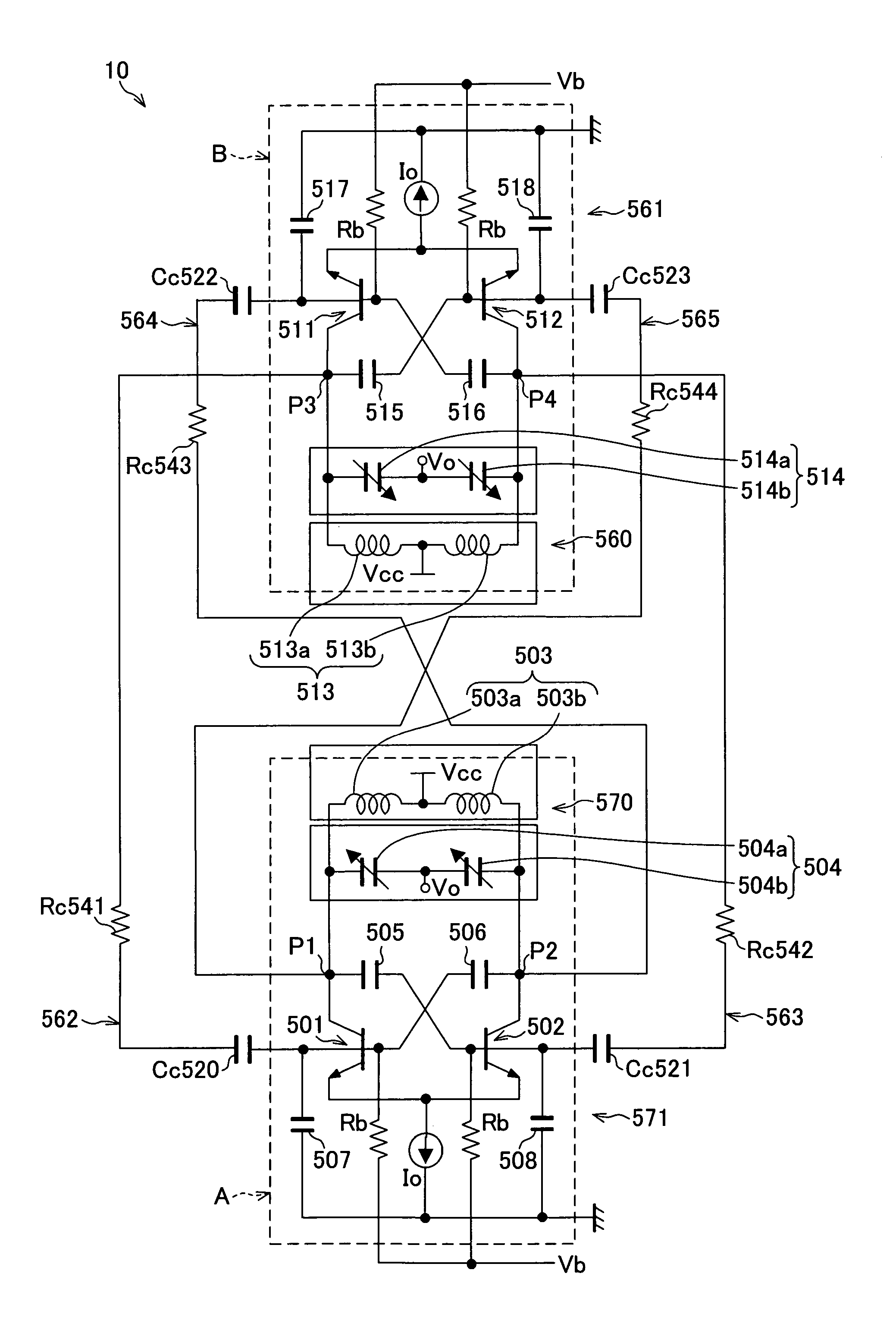
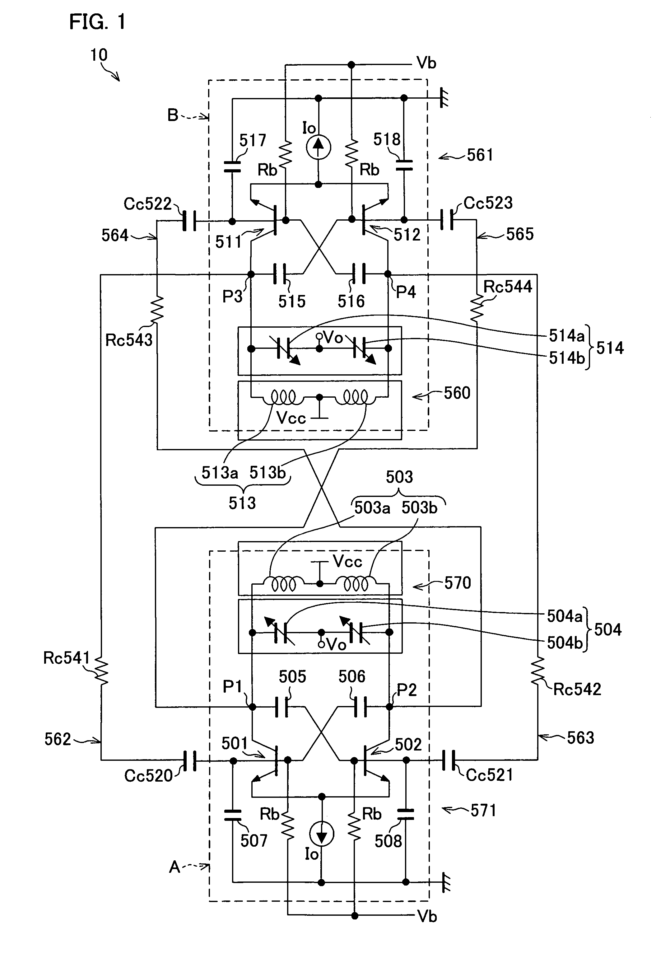
[0053]FIG. 1 is a circuit diagram illustrating a structure of an oscillator according to the present embodiment. As shown therein, an oscillator 10 (quadrature voltage controlled oscillator) includes a pair of an oscillator circuit A (first oscillator circuit) and an oscillator circuit B (second oscillator circuit) and four RC coupling networks 562 through 565. With this structure, the oscillator 10 generates four signals (quadrature signal) at P1 through P4. The four signals have 90° phase difference to each other.

[0054]The oscillator circuit A includes an LC resonant circuit 570 and a negative resistor circuit 571. The LC resonant circuit 570 includes a coil 503 (503a, 503b) and a varactor 504 (504a, 504b). The negative resistor circuit 571 includes two NPN transistors 501 and 502, four capacitors 505 (feedback capacitor), 506 (feedback capacitor), 507 and 508, two resistors Rb, and a current generator Io.

[0055]The coil 503a and 503b are connected in series, and the midpoint of th...

second embodiment

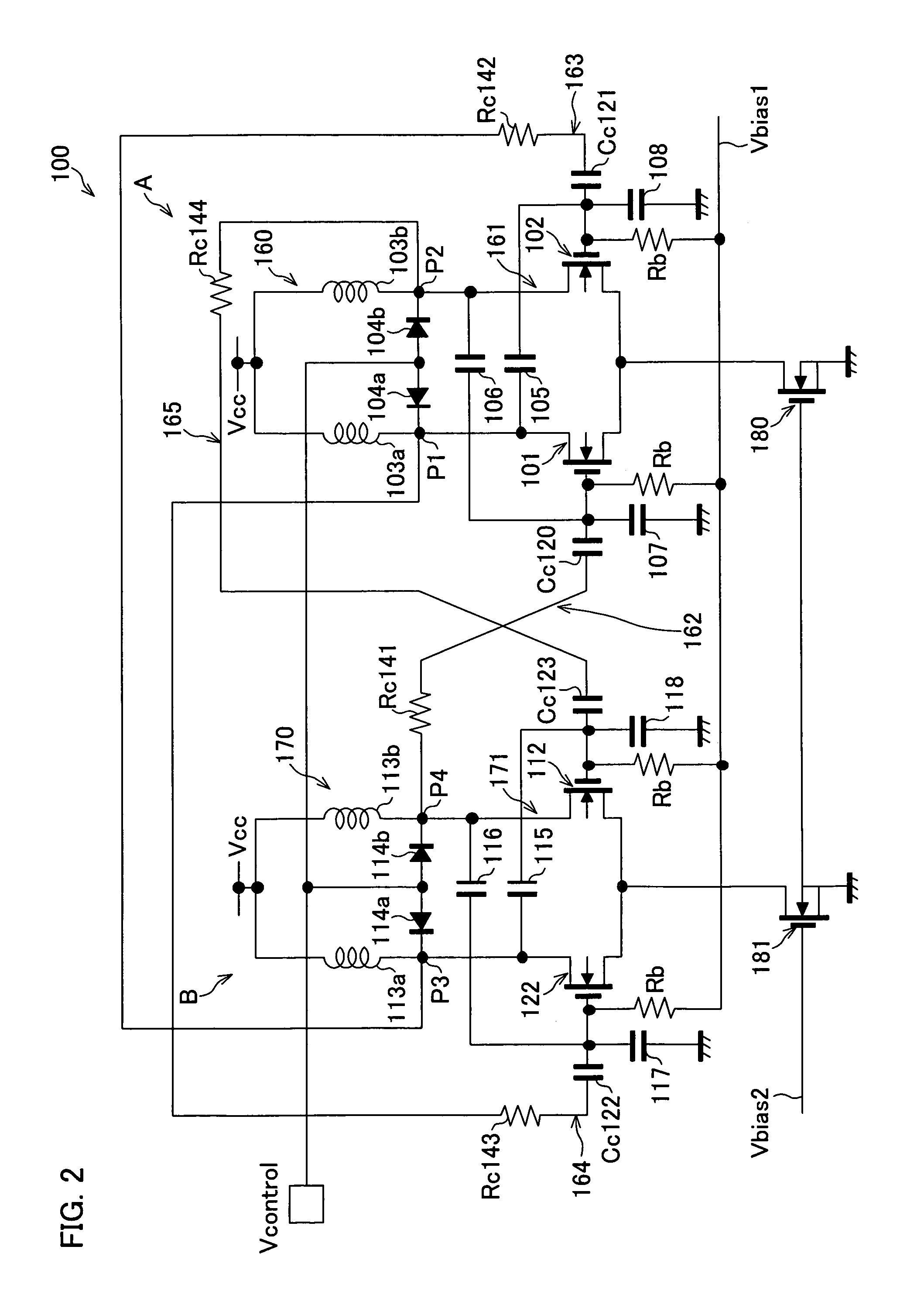
[0094]FIG. 2 illustrates another structure of the oscillator of the present invention. This structure includes a MOS transistor.

[0095]As shown therein, an oscillator 100 according to the present embodiment includes a pair of an oscillator circuit A (first oscillator circuit) and an oscillator circuit B (second oscillator circuit) and four RC coupling networks 162 through 165. With this structure, the oscillator 100 generates four signals (quadrature signal) at P1 through P4. The four signals have 90° phase difference to each other.

[0096]The oscillator circuit A includes an LC resonant circuit 160 and a negative resistor circuit 161. The LC resonant circuit 160 includes coils 103a and 103b, and variable capacitor diodes 104a and 104b. The negative resistor circuit 161 includes two N-channel MOS transistors 101 and 102 for use in cross-connection, four capacitors (feedback capacitor) 105, 106, 107 and 108, two resistors Rb, and an N-channel MOS transistor 180.

[0097]The coil 103a and 1...

third embodiment

[0116]FIG. 3 illustrates another modification example of the oscillator using the MOS transistors.

[0117]As shown in FIG. 3, an oscillator 200 according to the present embodiment includes a pair of oscillator circuit A (first oscillator circuit) and oscillator circuit B (second oscillator circuit), and four RC coupling networks 262 through 265. In the oscillator 200, four signals (four phase signals), 90° out of phase from one another, are respectively generated at P1 through P4.

[0118]The oscillator circuit A includes a LC oscillator circuit 260 and a negative resistor circuit 261. The LC oscillator circuit 260 includes coils 203a, 203b, and varactors (variable capacitance diodes) 204a, 204b. The negative resistor circuit 261 includes two N-channel MOS transistors 201 (sixth MOS transistor) and 202 (seventh MOS transistor) for cross-connecting, two N-channel MOS transistors 251 (fifth MOS transistor) and 252 (eighth MOS transistor) for coupling, two resistors Rb, and an N-channel MOS...


PUM


Abstract

The oscillator includes: a first oscillator circuit in which first and second transistors cross-connected to each other are connected to a resonant circuit; and a second oscillator circuit in which third and fourth transistors cross-connected to each other are connected to a resonant circuit, wherein a coupling capacitor and coupling resistor are serially provided between a collector terminal of the first transistor and a base terminal of the fourth transistor, and a coupling capacitor and coupling resistor are serially provided between a collector terminal of the second transistor and a base terminal of the third transistor, and a coupling capacitor and coupling resistor are serially provided between a collector terminal of the third transistor and a base terminal of the first transistor, and a coupling capacitor and coupling resistor are serially provided between a collector terminal of the fourth transistor and a base terminal of the second transistor. On this account, it is possible to suppress noises and reduce power consumption.

Description

[0001]This Nonprovisional application claims priority under 35 U.S.C. § 119(a) on Patent Application No. 307203 / 2004 filed in Japan on Oct. 21, 2004, the entire contents of which are hereby incorporated by reference.FIELD OF THE INVENTION[0002]The present invention relates to an oscillator, particularly to a voltage controlled oscillator for generating a quadrature signal.BACKGROUND OF THE INVENTION[0003]A communication device, such as a mobile phone, includes a voltage controlled oscillator as a local oscillator. The voltage controlled oscillator is required to have the accuracy of signal Generation (for example, quadrature signals which are 90° out of phase with each other), and in addition to this, a simpler circuit and lower power consumption for realizing a mobile system.[0004]FIGS. 9 to 15 show conventional structures of an oscillator for generating a quadrature signal.[0005]An oscillator (hereinafter referred to as a first conventional technique) shown in FIGS. 9(a) and 9(b) ...

Claims


Application Information

Patent Timeline
Patent Type & Authority Patents(United States)
IPC IPC(8): H03B27/00
CPCH03B27/00H03B5/1231H03B5/1296H03B5/1215H03B5/1243H03B5/1271
Inventor ADAN, ALBERTO O.
Owner SHARP KK
Why Eureka
Try Eureka