Unlock instant, AI-driven research and patent intelligence for your innovation.

Enhancement of the dynamic range of a multibit digital-to-analog converter

a multi-bit digital-to-analog converter and dynamic range technology, applied in the direction of analog-digital converters, instruments, transmission systems, etc., can solve the problems of reducing the dynamic range proportionally, the relatively higher output noise level of a system implementing a digital volume control in the digital signal processing portion of the chain of functional blocks of the system, and the no longer attenuated noise and distortion of the dac. to achieve the effect of preventing the introduction of any arti

Active Publication Date: 2007-07-03
STMICROELECTRONICS SRL
View PDF4 Cites 9 Cited by
  • Summary
  • Abstract
  • Description
  • Claims
  • Application Information

AI Technical Summary

Benefits of technology

The patent describes a method to improve the dynamic range of a digital-to-analog converter (DAC) in an audio system. The method uses a compressor / expander to reduce the noise content at low input signal levels. This helps to recover the dynamic range that would be lost if the volume control were applied upstream of the DAC. The method can be easily and economically implemented and can seamlessly complement other techniques such as noise shaping and DEM algorithms. The method involves multiplying the incoming digital codes of the pulse code modulated signal by a factor and scaling the amplitude of the current contributions from the DAC by the same factor. This results in a dynamic range enhancement of the output analog signal while reducing the noise introduced by the DAC.

Problems solved by technology

However, the choice of implementing the volume control in the digital signal processing part of the audio system, upstream of the DAC interface of the output power amplifier, has trade offs.
Notably, the noise and distortion that are produced in the DAC are no longer attenuated by the analog volume control.
In practice, in case of such “fully” digital systems, the output noise and distortion are generally higher than that of a comparable traditional system with analog volume control operating downstream of the DAC.
The relatively higher output noise level of a system implementing a digital volume control in the digital signal processing portion of the chain of functional blocks of the system reduces proportionally the dynamic range.

Method used


Image

  • Enhancement of the dynamic range of a multibit digital-to-analog converter
  • Enhancement of the dynamic range of a multibit digital-to-analog converter
  • Enhancement of the dynamic range of a multibit digital-to-analog converter

Examples


Embodiment Construction

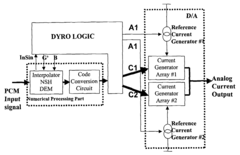
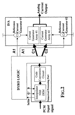
[0032]FIG. 2 is a representation of a digital-to-analog converter, detailing the numerical processing part and the analog output part, D / A, respectively identified by the two distinct dotted line perimeters, and of the additional logic circuit, DYRO LOGIC, implementing this invention. The digital-to-analog converter of FIG. 2 may include the DAC “interface” between the “DSP with Digital Volume Control” and the “Power Amplifier” of an audio system, according to the relevant part (2) of FIG. 1.

[0033]Solely for illustration purposes, the DAC will be considered to be of the so-called thermometric code conversion type, employing N elementary current sources individually selectable and, in the example considered, organized in two subsets, namely: Array#1 and Array#2, each including N / 2 elementary current generators, nominally identical to one another.

[0034]The block DYRO LOGIC comprises a logic circuit for monitoring the value of the sampled numerical codes of the pulse code modulated sig...


PUM


Abstract

A digital-to-analog converter (DAC) for an audio system may include at least first and second subsets of individually selectable elementary current sources for delivering analog output current contributions, a code conversion circuit for selecting elementary current sources of first and second subsets as a function of codes of a pulse code modulated (PCM) input signal. The DAC may multiply by a certain factor incoming codes of the PCM signal after their value has remained lower than a threshold for a certain period of time and for as long as their value equals or surpasses the threshold value, and may correspondingly scale and de-scale by the same factor the amplitude of the analog output current contributions produced by the elementary current sources of the two subsets.

Description

FIELD OF THE INVENTION[0001]The present invention relates to a method for enhancing the dynamic range of a multibit digital-to-analog converter (briefly DAC), particularly useful, though not exclusively, for audio applications.BACKGROUND OF THE INVENTION[0002]Digital-to-analog conversion for audio applications is performed by generating the output analog signal as the sum, at each sampling instant, of a given number of elementary quantities or contributions, which may be, for example, currents supplied by elementary current generators or generated by means of resistors, or charges stored in capacitors. Digital-to-analog conversion can be roughly divided in two major categories according to the approach adopted in the conversion namely either “thermometric” or “binary” coding.[0003]In thermometric coding, the elementary contributions used for generating the output analog signal assume values identical to one another and are generated by distinct sources numbering N, where N=2n repres...

Claims


Application Information

Patent Timeline
Patent Type & Authority Patents(United States)
IPC IPC(8): H03M1/62
CPCH03M1/70
Inventor GROSSO, ANTONIOMERONI, CRISTIANOBOTTI, EDOARDO
Owner STMICROELECTRONICS SRL
Features
  • R&D
  • Intellectual Property
  • Life Sciences
  • Materials
  • Tech Scout
  • Unparalleled Data Quality
  • Higher Quality Content
  • 60% Fewer Hallucinations
Learn More