Optical fiber, dispersion compensator, and optical transmission system
- Summary
- Abstract
- Description
- Claims
- Application Information
AI Technical Summary
Benefits of technology
Problems solved by technology
Method used
Image
Examples
first embodiment
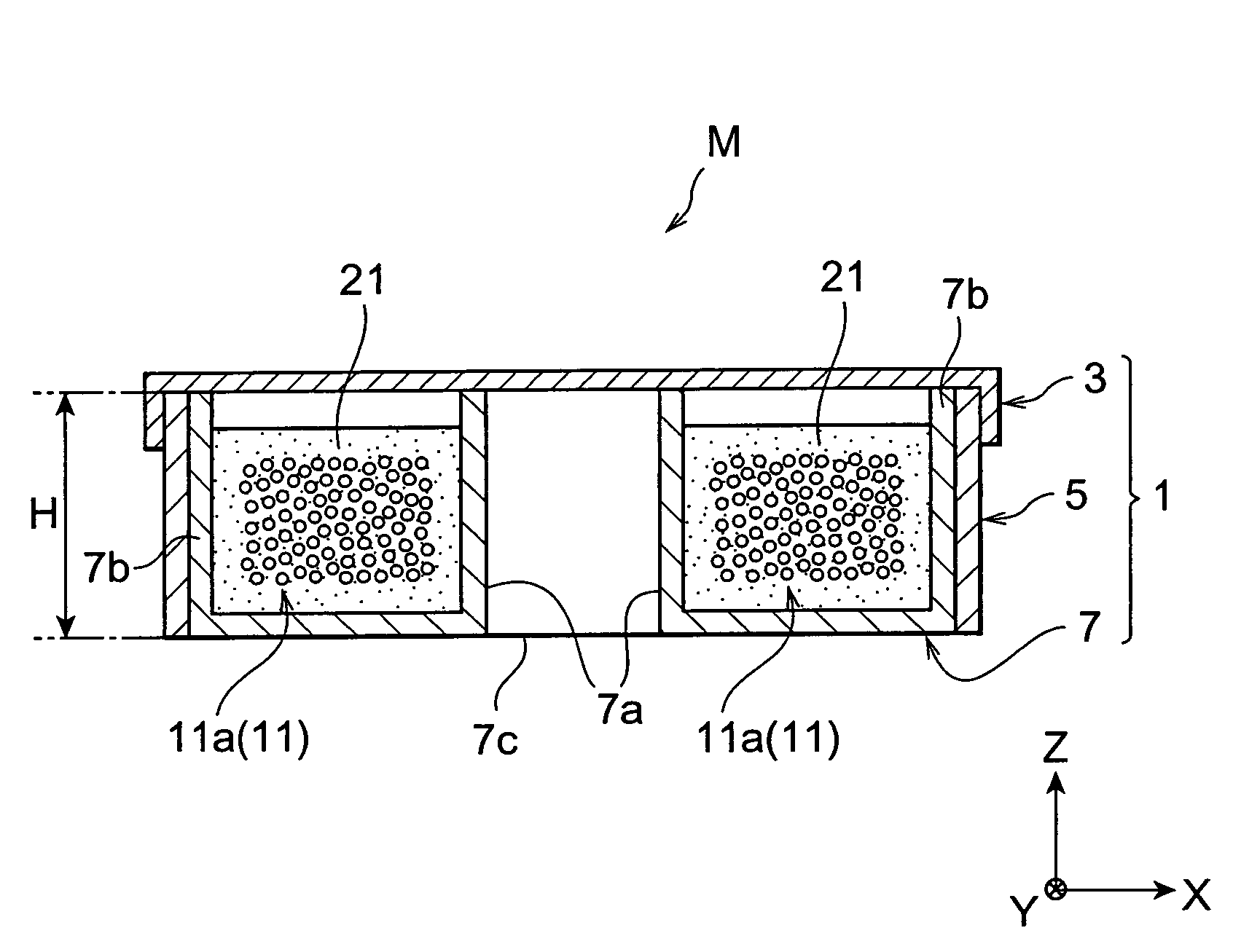
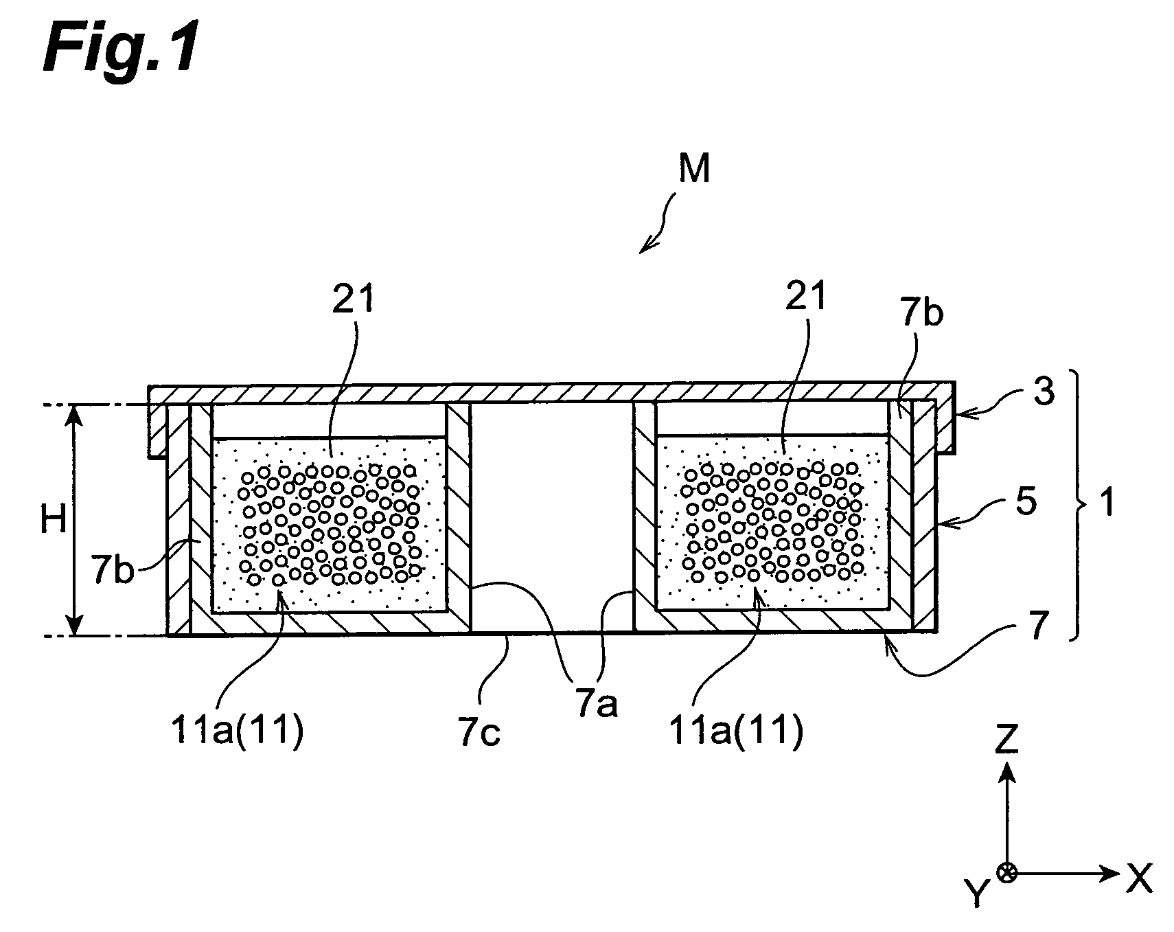
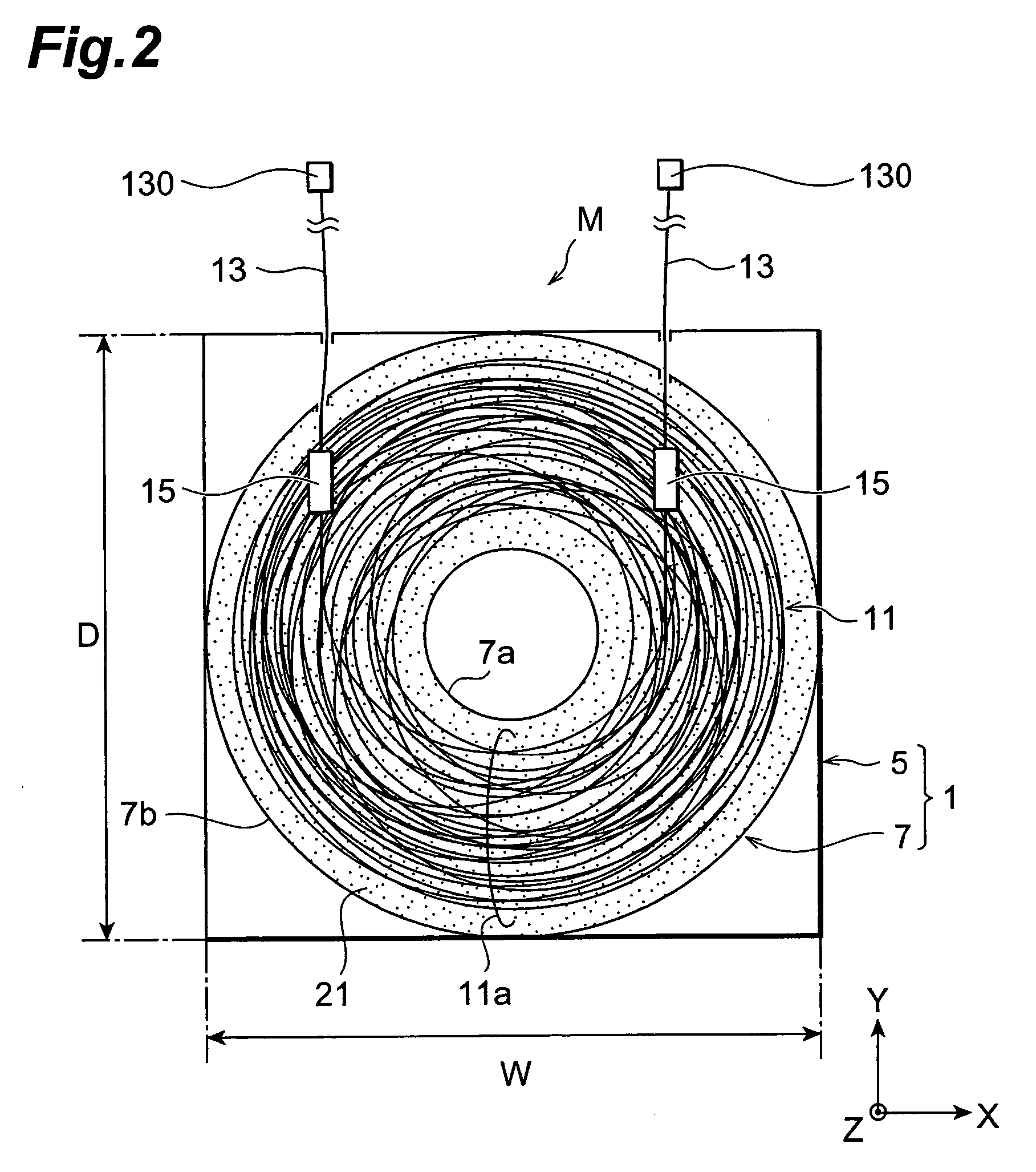
[0135]As shown in FIG. 12A, the optical transmission system 51 comprises a transmitter 53 for transmitting multiplexed signal light, a transmission optical fiber 55 through which the signal light propagates, a dispersion compensator M having the structure mentioned above (dispersion compensator according to the present invention), and a receiver 57 for receiving the signal light. In the configuration of FIG. 12A, the dispersion compensator M is connected between the transmitter 53 and the transmission optical fiber 55. The transmission optical fiber 55 has a length of 50 km or shorter, whereas the signal wavelength band is the 1.55-μm band.
[0136]Due to such a configuration, in the optical transmission system 51, the chromatic dispersion of the transmission optical fiber 55 is canceled or compensated for by the dispersion compensator M, so that the absolute value of chromatic dispersion in the whole optical transmission line between the transmitter 53 and receiver 57 becomes smaller...
second embodiment
[0138]The dispersion compensator M may be constituted by a plurality of dispersion compensating modules each having the structure mentioned above (shown in FIGS. 1 to 6). In the optical transmission system 51 as shown in FIG. 13A, the dispersion compensator M may be constructed such that a plurality of dispersion compensating modules M1 to M3 are connected in series, so as to regulate chromatic dispersion values. When a plurality of dispersion compensating modules M1 to M3 are connected in series as such, the dispersion compensating modules M1 to M3 may have either identical or different chromatic dispersion values. A plurality of dispersion compensating modules M1 to M3 may be disposed on the receiver 57 side of the transmission optical fiber 55 as a matter of course.
[0139]In the optical transmission system 51 according to the second embodiment, as shown in FIG. 13B, an optical demultiplexer 55a for separating multiplexed signal light into individual signal channels and an optical...
third embodiment
[0140]As shown in FIG. 14, the optical transmission system 61 includes a plurality of transmitters 53 and a plurality of receivers 57, and further comprises an optical multiplexer 63 for combining a plurality of signal light components transmitted from the respective transmitters 53, and an optical demultiplexer 65 for separating thus multiplexed signal light into a plurality of signal light components. In this optical transmission system 61, though optical amplifiers 67 are connected to the upstream stage (on the transmitter 53 side) and downstream stage (on the receiver 57 side) of the transmission optical fiber 55, respectively, they may be connected to one or none of these stages as well. The signal wavelength band is the 1.55-μm band in the optical transmission system 61 as well.
[0141]The dispersion compensator according to the present invention is not restricted to the above-mentioned embodiments. For example, the housing 1 may have a polygonal form without being restricted t...
PUM
 Abstract
Description
Claims
Application Information
 - R&D
- Intellectual Property
- Life Sciences
- Materials
- Tech Scout
- Unparalleled Data Quality
- Higher Quality Content
- 60% Fewer Hallucinations
Browse by: Latest US Patents, China's latest patents, Technical Efficacy Thesaurus, Application Domain, Technology Topic, Popular Technical Reports.
© 2025 PatSnap. All rights reserved.Legal|Privacy policy|Modern Slavery Act Transparency Statement|Sitemap|About US| Contact US: help@patsnap.com


