Gyrostabilizer for small boats

a gyrostabilizer and small boat technology, applied in special-purpose vessels, instruments, transportation and packaging, etc., can solve the problems of people and animals experiencing motion sickness, inefficient at low speeds, and prior gyroscope-related anti-rolling systems that are too large for relatively small vessels, so as to reduce ship roll motion and reasonable stabilization

Inactive Publication Date: 2007-07-10
AKERS RICHARD H +1
View PDF23 Cites 26 Cited by
  • Summary
  • Abstract
  • Description
  • Claims
  • Application Information

AI Technical Summary

Benefits of technology

[0014]With the rotor in its nominal position, the counter torque is proportional to the angular momentum of the spinning object, multiplied by the angular velocity of the entire mechanism around the secondary axis. This invention can create a larger counter roll torque than the conventional technology because the angular momentum of the machine is much larger than that of a conventional machine. Conventional technology for a ship stabilizer using gyroscopic stabilization includes a flywheel drive motor system whose speed is determined by a constant voltage. This invention uses motor controlled by an active servo system. The active control system reduces the time required for the drum to spin up to operating speed and to spin down to a full stop, when compared to the times that would be obtained using a constant voltage drive motor.
[0015]Conventional technology for a ship stabilizer using gyroscopic stabilization includes a flywheel spinning in ambient air, and during full-speed operation most of the rotor energy loss comes from air drag. The rotating drum in this invention is enclosed in a chamber with reduced air pressure, reducing the energy required to operate the machine. This chamber also acts as a protective shroud, so that failures in the rotor will be contained in the shroud chamber.
[0018]The present invention fills the need for a stabilization system that may be used to counteract rolling caused by wave and wake action. The invention is an active gyrostabilizer that fits within the dimensions of a boat or small ship and achieves reasonable stabilization under the majority of sea conditions experienced by boats and small ships. The gyrostabilizer of this invention includes a rotor rotated by a rotor motor that is actively controlled by a motor control system. As indicated, in addition to regulating and generating rotor spin, the rotor motor and the motor control system act as a rotor braking system so that the gyrostabilizer can be spun down quickly as needed. The system of the present invention also preferably includes one or more angular rate sensors and one or more inclinometers to sense the exact roll position and angular velocity. In particular, solid-state angular inclinometers and rate sensors can be used to sense the boat's motion. The active control system uses information from the sensors to drive the gimbal's servomotor to control the gyrostabilizer's gimbal angle.

Problems solved by technology

A rolling boat is uncomfortable and can cause people and animals to experience motion sickness.
The difficulty with creating such a device is that a boat is not resting on or in a solid medium that can be used as a base to create an anti-rolling moment.
Although the device performed as expected, the Navy stopped installing gyrostabilizers at the onset of WW I. Some gyrostabilizers were installed on private yachts in the first part of the 20th century, but other methods of stabilization supplanted gyrostabilizers in the yacht market.
Fins, interceptors, and foils all depend on significant forward motion for their anti-roll forces, and are inefficient at low speeds.
Prior gyroscope-related anti-rolling systems have either been too massive for relatively smaller vessels, such as yachts, or have been confined to use as a sensing system in combination with a structural element or elements that actually do the stabilizing.

Method used


Image

  • Gyrostabilizer for small boats
  • Gyrostabilizer for small boats
  • Gyrostabilizer for small boats

Examples


first embodiment

[0043]In reference to FIG. 4, the drum (2) is fastened to axle (7) by webs (16). A web is a radial plate such as the end caps of a drum, whose purpose is to attach the outer drum surface to the axle. The axle / drum assembly spins around axis (15). The drum (2) is larger than the inner webs (16), which are attached inside the ends of the drum.

second embodiment

[0044]In reference to FIG. 5, the drum (2) is fastened to axle (7) by webs (16). The axle / drum assembly spins around axis (15). The web (16) is the same diameter as the drum (2), and the drum spans the space between webs.

third embodiment

[0045]In reference to FIG. 6, the drum (2) is fastened to axle (7) by three or more webs (16). The axle / drum assembly spins around axis (15). The drum (2) is larger than the inner webs (16), which are attached inside the drum.

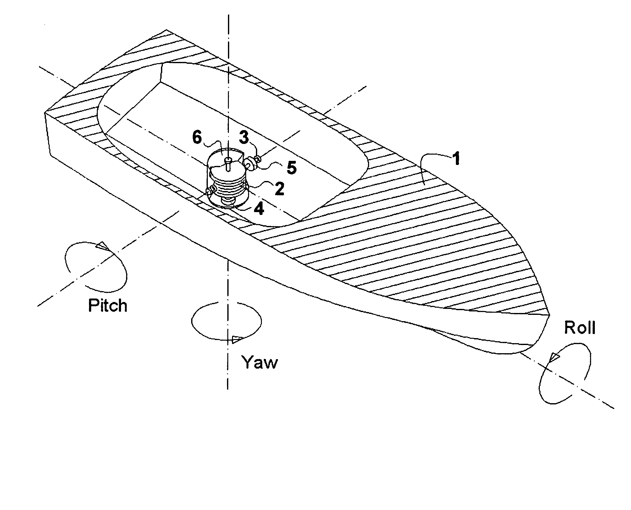
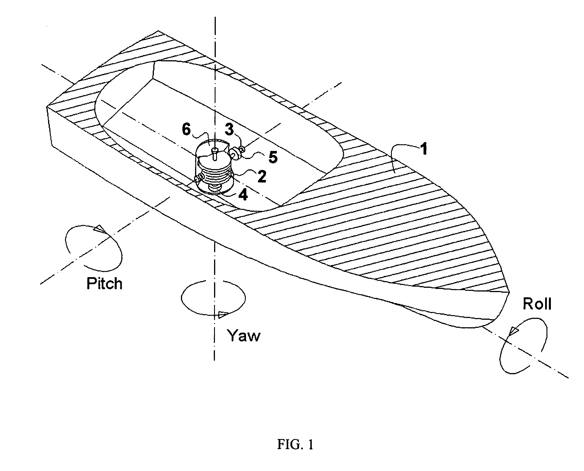
[0046]In reference to FIG. 7, in a second embodiment of the gyrostabilizer system of the present invention, the motor (4) again spins the gyrostabilizer drum (2) at constant, high speeds and the drum spins in bearings in the shroud (6). The shroud, drum and spin motor assembly has gimbals (3), and the gimbals are mounted to the boat (1). Angular motion of the shroud, drum and spin motor assembly around the gimbal axis is controlled by servo motor (5). Roll angle and roll rate are measured by sensors and information from these sensors is input to an active controller that drives the servo motor. In this embodiment the gimbal axis is coincident or parallel with the yaw axis of the boat or ship (1).

[0047]In reference to FIG. 8, in a third embodiment of the gyrosta...


PUM


Abstract

A gyrostabilizer system that counteracts the natural rolling motion of a small boat or vessel. The invention constitutes an improvement in prior art systems of this type in that the system weighs less because it has a much lighter rotor made of composite materials spinning at much higher speeds. The gyrostabilizer system includes a lightweight rotor spinning at very high speeds to attain a large angular momentum. The mass of the rotor is concentrated away from the spin axis of the rotor to maximize angular momentum while minimizing weight. The rotor is mounted in a frame that, in turn, is mounted on gimbals so that the frame can be rotated about an axis that is normal to the longitudinal roll axis of the vessel. When the rotor is rotated about the gimbals, a torque is created that opposes the torque created by the sea and reduces the rolling motion of the vessel. The rotor may be mounted in an evacuated chamber to reduce air drag. Rotation of the rotor frame around the gimbal axis is controlled by an active servo system using information provided by roll angular position and angular velocity sensors.

Description

CROSS REFERENCE TO RELATED APPLICATION[0001]The present application claims the priority benefit of U.S. provisional patent application Ser. No. 60 / 509,653, filed Oct. 8, 2003, entitled “GYROSTABILIZER FOR SMALL BOATS” of the same named inventor. The entire contents of that prior application are incorporated herein by reference.BACKGROUND OF THE INVENTION[0002]1. Field of the Invention[0003]The present invention relates to systems and devices for stabilizing boats and small ships. More particularly, the present invention relates to gyroscopic stabilizers positioned in boats and configured to counteract rolling motion caused by waves and ship wakes. The gyroscopic stabilizer of the present invention is an active stabilization device.[0004]2. Description of the Prior Art[0005]A rolling boat is uncomfortable and can cause people and animals to experience motion sickness. A device that can create an anti-roll torque can be used to oppose this motion. The difficulty with creating such a d...

Claims


Application Information

Patent Timeline
Patent Type & Authority Patents(United States)
IPC IPC(8): B63B39/00B63B39/04G01C19/30
CPCB63B39/04Y10T74/1254
Inventor AKERS, RICHARD H.
Owner AKERS RICHARD H
Why Eureka
Try Eureka