Threading tap for cutting threads in blind holes and methods of its manufacture

a technology for cutting threads and taps, applied in the direction of manufacturing tools, wood boring tools, transportation and packaging, etc., can solve the problems of chips getting entangled in the coated flutes, known taps suffer from drawbacks, etc., and achieve the effect of improving the properties of the tap regarding the threading properties

Active Publication Date: 2007-07-10
SANDVIK INTELLECTUAL PROPERTY AB
View PDF18 Cites 9 Cited by
  • Summary
  • Abstract
  • Description
  • Claims
  • Application Information

AI Technical Summary

Benefits of technology

[0011]Suitably, the helix angle, i.e. the angle of the flute relative to the axis is between 46° and 50°. In particular, the helix angle is between 48° and 50°. Hereby is achieved an even further improved chip evacuation, due to increased room for the chips, such that holes having a depth three times deeper than the diameter of the tap can be threaded. Helix angles smaller than 48° may cause less room for chip transportation, whereas helix angles larger than 50° may cause the vertical component of chip speed to be low. The optimal helix angle has proven to be 48°.
[0012]Advantageously, the thread is back-tapered (chamfered) towards the rear end. In particular the taper angle of the chamber is between 8° and 11°. Hereby is achieved an improved tap feeding during inversion moment, i.e. when the tap is removed from the hole, and furthermore a reduced absorbed torque.
[0015]Preferably, the thread cutting structure is coated by physical vapor deposition coating. In particular, the coating comprises one of TiCN, TiN, TiAlN, TiAlCN or CrN. Alternatively, a multi-layer coating such as a combination of TiAlN and WC / C (tungsten carbon and carbide, having a low hardness and low friction coefficient) may be used. Hereby, an extended life of the threads is achieved. It should be noted that the flutes are not coated by such a material, since this would cause wider and more irregular chips that get entangled in the flutes. Best performance on work-pieces made of carbon and construction steel is achieved by the use of TiAlN, whereas on stainless steel work-pieces, the best performance is achieved by the above mentioned multi-layer coating of TiAlN and WC / C.

Problems solved by technology

However, the known taps suffer from the drawback that chips get entangled in the coated flutes when working in carbon steel, construction steel or stainless steel.

Method used


Image

  • Threading tap for cutting threads in blind holes and methods of its manufacture
  • Threading tap for cutting threads in blind holes and methods of its manufacture
  • Threading tap for cutting threads in blind holes and methods of its manufacture

Examples


first embodiment

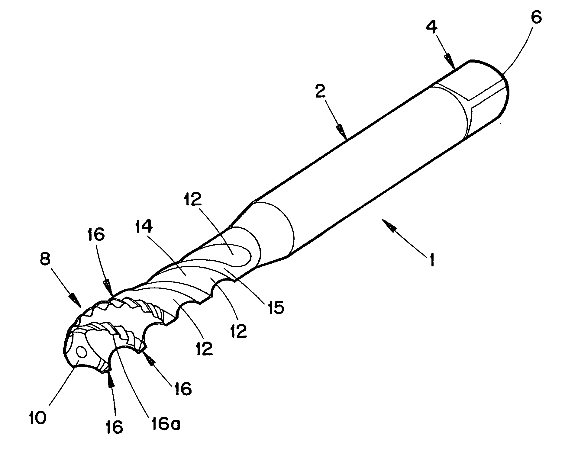
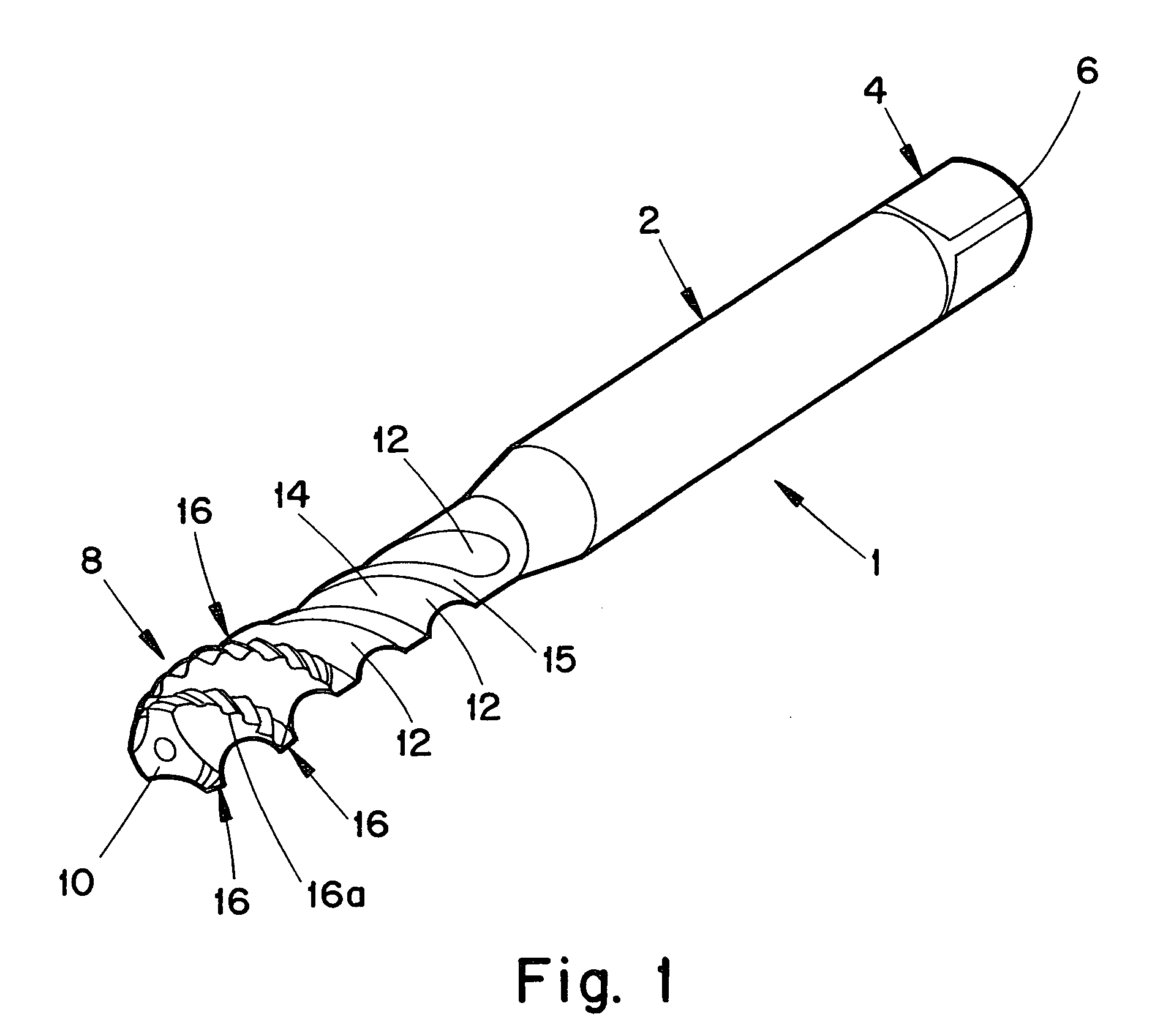
[0023]FIG. 1 shows a tap 1 having an elongated body 2 with a connector portion 4 at a first or rear end region 6, and a toothed threading portion 8 at a second or front end region 10. The threading portion 8 comprises three helical threads 16 and three helical flutes 12, the flutes being defined by helical flanks 14 of the threads. The outer peripheries of the threads 16 have cutting teeth 16a formed thereon in the front end region 10. Portions of the threads extend rearwardly of the front region 10, and the outer peripheries of such portions are defined by flat (non-teethed) surfaces 15. The teeth 16a are aligned helically about the circumference of the body to define a helical thread-cutting structure that is interrupted by the flutes 12.

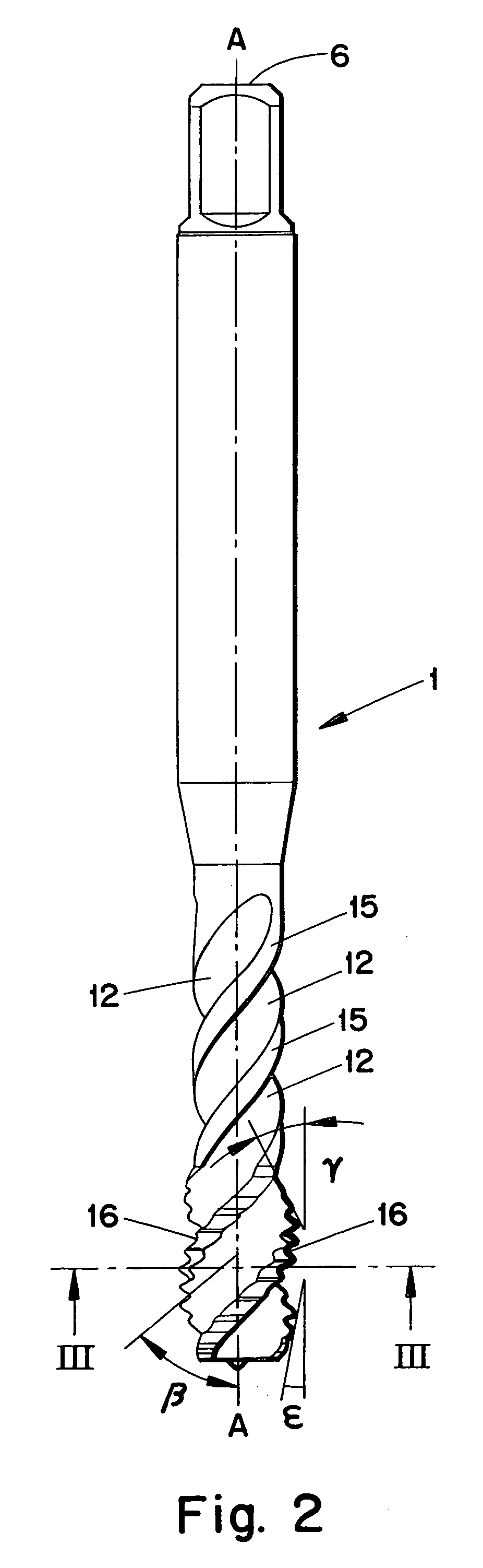
[0024]In FIG. 2, a central axis of rotation A—A is shown. A helix angle β is shown as an angle formed between the extension of a flute and the axis A—A and is from 46°–55°, more preferably 48°–50° and most preferably 48°. Furthermore it shown how ...

second embodiment

[0027]FIGS. 4–5 show a tap 1A which is similar to that of FIGS. 1–3, except that, instead of there being three threads and three flutes, there are provided four threads 16 and four flutes 12 defined by the flanks 14.

[0028]Regarding both embodiments described above, it is desirable to achieve extended life of the thread. This is conventionally performed by coating the thread by a physical vapor deposition coating (PVD), such as TiCN, TiN, TiAlN, TiAlCN or CrN, or a multi-layer coating such as a combination of TiAlN and WC / C (tungsten carbon / carbide, having a low hardness and low friction coefficient), called TiAlN / WC / C.

[0029]However, it has turned out that it is disadvantageous to have such a coating in the flutes, i.e. on the flanks, since the chips produced by such coated flutes are undesirably wide and irregular.

[0030]In accordance with the present invention, the exposed (uncoated) surfaces of the flanks are stream tempered. By using uncoated flutes, narrower and more regular chi...


PUM

PropertyMeasurementUnit
helix angleaaaaaaaaaa
temperatureaaaaaaaaaa

Abstract

A threading tap for cutting threads in blind holes includes an elongated body with a central axis, the body having at a rear end a connector portion, and having at a front end a threading portion. The threading portion is provided with at least one helical thread-cutting structure and interconnected flank portions defining at least one helical flute which interrupts the helical thread cutting structure. The flank portions present exposed surfaces that are steam tempered. The rest of the tap is coated by PVD.

Description

BACKGROUND OF THE INVENTION[0001]This application claims priority under 35 U.S.C. §§ 119 and / or 365 to Patent Application Serial No. 0300224-3 filed in Sweden on Jan. 30, 2003, the entire content of which is hereby incorporated by reference.[0002]The present invention relates to a threading tap for cutting threads in blind holes, comprising an elongated body with a central axis and having at a first end a connector portion and at a second end a threading portion. The threading portion is provided with at least one helical thread extending about the circumference of said body. Flank portions of the thread define a helical flute which interrupts the helical thread.[0003]The invention also relates to a method of manufacturing such a tap.[0004]Such a tap and such a method are known from EP-A-0 641 620 (corresponding to U.S. Pat. No. 5,487,626), wherein the tap is provided with a wear resistant coating. However, the known taps suffer from the drawback that chips get entangled in the coat...

Claims


Application Information

Patent Timeline
Patent Type & Authority Patents(United States)
IPC IPC(8): B23G5/06
CPCB23G5/06B23G2200/48B23G2225/28B23G2225/32B23G2225/52Y10T408/904B23G2225/60B23G2240/36Y10T408/78Y10T408/90467Y10T408/9048B23G2225/56
Inventor MALAGNINO, GIOVANNATROILO, ROBERTO
Owner SANDVIK INTELLECTUAL PROPERTY AB
Why Eureka
Try Eureka