Control method for downhole steering tool

a control method and steering tool technology, applied in the direction of directional drilling, borehole/well accessories, surveys, etc., can solve the problems of reducing limiting both the frequency of survey data available, and at best difficult sustained control, so as to improve the control of the drilling process, reduce the tortuosity of the borehole, and save the communication bandwidth.

Active Publication Date: 2007-07-17
SCHLUMBERGER TECH CORP
View PDF29 Cites 73 Cited by
  • Summary
  • Abstract
  • Description
  • Claims
  • Application Information

AI Technical Summary

Benefits of technology

[0010]Exemplary embodiments of the present invention may advantageously provide several technical advantages. For example, exemplary methods according to this invention enable the RCLD of the borehole to be determined independent of the rate of penetration or total vertical depth of the borehole. As such, embodiments of this invention tend to minimize the need for communication between a drilling operator and the bottom hole assembly, thereby advantageously preserving downhole communication bandwidth. Furthermore, embodiments of this invention enable control data to be acquired at significantly increased frequency, thereby improving the control of the drilling process. Such improved control may reduce tortuosity of the borehole and may therefore tend to minimize (or even eliminate) the need for expensive reaming operations.

Problems solved by technology

While such procedures have been utilized successfully in various drilling operations, both tend to be limited by the typically scarce downhole communication bandwidth (e.g., mud pulse telemetry bandwidth) available in drilling operations.
Telemetry bandwidth constraints tend to reduce the frequency of survey data available for control of the steering tool.
Such time delays render sustained control difficult at best and may lead to more tortuous borehole profiles that sometimes require costly and time consuming reaming operations.
Such complexity tends to increase both fabrication and maintenance costs and inherently reduces reliability (especially in the demanding downhole environment).
Furthermore, the magnitude of the curvature is inadequate to fully define a change in the longitudinal direction of a borehole.
Moreover, since the method disclosed by Barr et al. depends on distance measurements between the borehole wall and a downhole tool, the accuracy of the curvature measurements may be significantly compromised in boreholes having a rough surface (e.g., in formations in which there is appreciable washout during drilling).
Another potential source of error is related to the length of the structure to which the distance sensors are mounted.
If the structure is relatively short, then the curvature of the borehole is measured along an equally short section thereof and hence subject to error (e.g., via local borehole washout or turtuosity).
On the other hand, if the structure is relatively long, then measurement of its curvature becomes complex (e.g., possibly requiring numerous strain gauges) and hence prone to error.

Method used


Image

  • Control method for downhole steering tool
  • Control method for downhole steering tool
  • Control method for downhole steering tool

Examples


Embodiment Construction

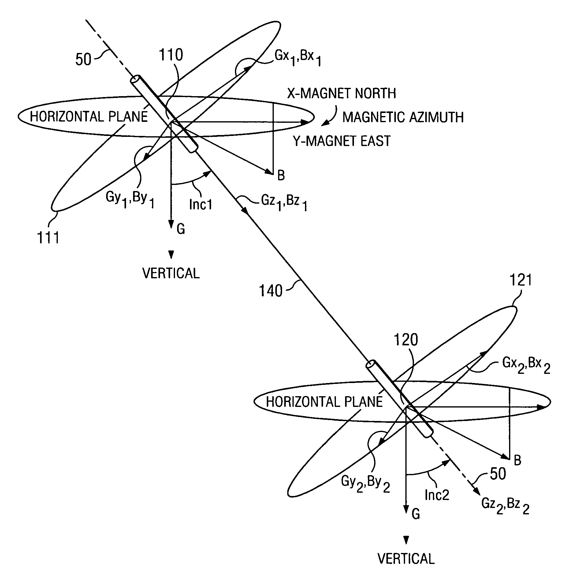
[0020]It will be appreciated that aspects of this invention enable the rate of change of the longitudinal direction (RCLD) of a borehole to be measured. It will be understood by those of ordinary skill in the art that the RCLD of a borehole is typically fully defined in one of two ways (although numerous others are possible). First, the RCLD of a borehole may be quantified by specifying the build rate and the turn rate of the borehole. Where used in this disclosure the term “build rate” is used to refer to the vertical component of the curvature of the borehole (i.e., a change in the inclination of the borehole). The term “turn rate” is used to refer to the horizontal component of the curvature of the borehole (i.e., a change in the azimuth of the borehole). The RCLD of a borehole may also be quantified by specifying the dogleg severity and the tool face of the borehole. Where used in this disclosure the term “dogleg severity” refers to the curvature of the borehole (i.e., the sever...


PUM


Abstract

A method for determining a rate of change of longitudinal direction of a subterranean borehole is provided. The method includes positioning a downhole tool in a borehole, the tool including first and second surveying devices disposed thereon. The method further includes causing the surveying devices to measure a longitudinal direction of the borehole at first and second longitudinal positions and processing the longitudinal directions of the borehole at the first and second positions to determine the rate of change of longitudinal direction of the borehole between the first and second positions. The method may further include processing the measured rate of change of longitudinal direction of the borehole and a predetermined rate of change of longitudinal direction to control the direction of drilling of the subterranean borehole. Exemplary embodiments of this invention tend to minimize the need for communication between a drilling operator and the bottom hole assembly, thereby advantageously preserving downhole communication bandwidth.

Description

FIELD OF THE INVENTION[0001]The present invention relates generally to directional drilling applications. More particularly, this invention relates to a control system and method for controlling the direction of drilling.BACKGROUND OF THE INVENTION[0002]In oil and gas exploration, it is common for drilling operations to include drilling deviated (non vertical) and even horizontal boreholes. Such boreholes may include relatively complex profiles, including, for example, vertical, tangential, and horizontal sections as well as one or more builds, turns, and / or doglegs between such sections. Recent applications often utilize steering tools including a plurality of independently operable force application members (also referred to as blades or ribs) to apply force on the borehole wall during drilling to maintain the drill bit along a prescribed path and to alter the drilling direction. Such force application members are typically disposed on the outer periphery of the drilling assembly ...

Claims


Application Information

Patent Timeline
Patent Type & Authority Patents(United States)
IPC IPC(8): E21B47/022E21B44/00E21B7/04E21B47/00
CPCE21B7/04E21B47/022
Inventor BARON, EMILIOJONES, STEPHEN
Owner SCHLUMBERGER TECH CORP
Why Eureka
Try Eureka