Digital burette and method for displaying the dose volume in said digital burette

US7244397B2Active Publication Date: 2007-07-17HIRSCHMANN LABORGERATE

Image

  • Digital burette and method for displaying the dose volume in said digital burette
  • Digital burette and method for displaying the dose volume in said digital burette
  • Digital burette and method for displaying the dose volume in said digital burette

Examples


Embodiment Construction

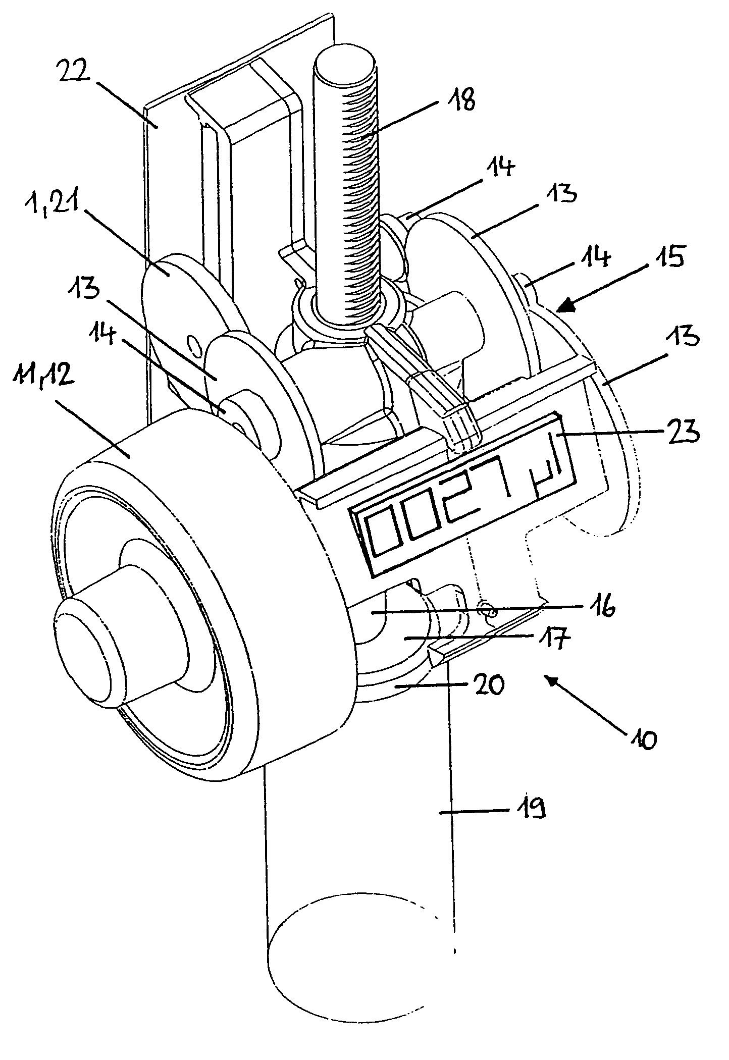
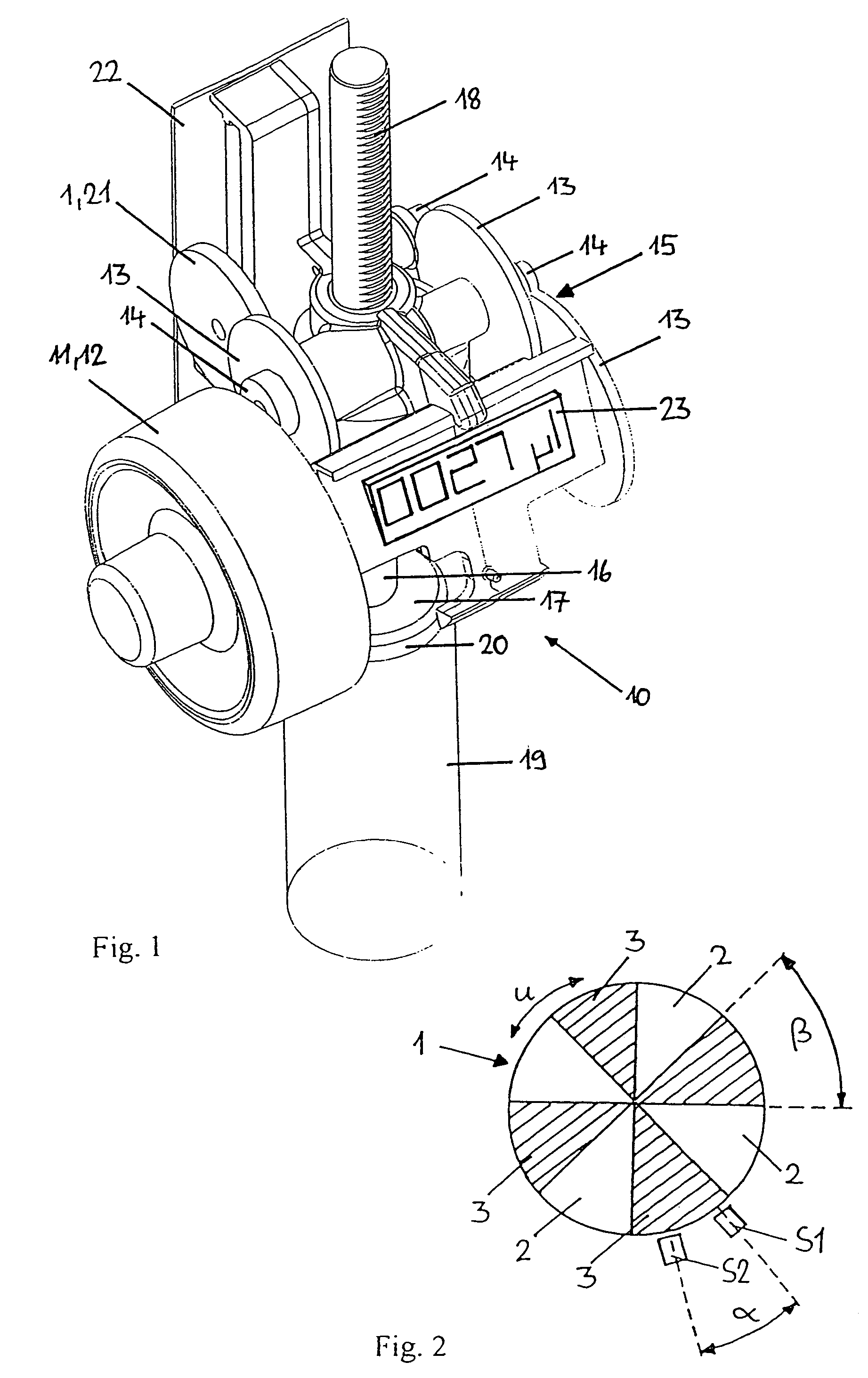
[0037]FIG. 1 shows a drive block 10 disposed in the head of a digital burette. The drive block 10 has a manual drive 11 in the form of a rotating handle 12. An identical rotating handle is optionally located on the opposite side, disposed on a common axle. The axle is connected to a piston rod 16 of a lifting piston 17 via a mechanical gear 15 formed from toothed wheels 13 and pinions 14. The piston rod 16 has teeth 18 in its upper section facing the output side of the gear 15. The lifting piston 17 is guided in a pipetting channel 19 and sealed with respect thereto by means of a sealing lip 20 to suction or discharge the desired liquid volume.

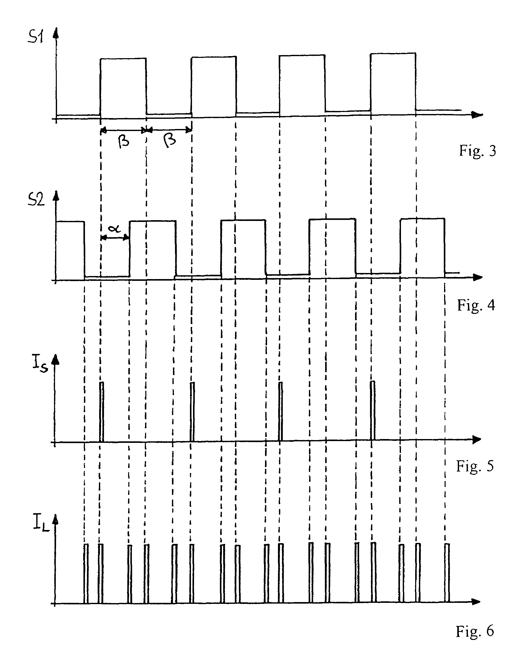
[0038]To detect the dose volume which corresponds to the number of turns of the turning handle 12, a control is provided with an incremental encoder 21, which is operatively connected to the gear 15, in the form of a sector disc 1 (FIG. 2) having two groups of sectors 2, 3 of different magnetic field strength which are alternately disposed in ...


PUM


Abstract

The invention relates to a digital burette having a manual drive for suctioning and applying an adjustable dose volume, a gear unit connected downstream and a digital display device controlled thereby for setting the dose volume. The control comprises an incremental encoder which is functionally connected to the gear unit, at least one sensor for detecting the signals produced by the incremental encoder and a processor connected to the sensor and the display device for calculating the dose volume corresponding to the number of signals. The incremental encoder is, in particular, a sector disc with two groups of sectors of different magnetic field strength disposed alternately in the peripheral direction of the sector disc. A sensor detects the number of turns of the sector disc. To save energy, the power supply of the burette is ensured by a solar cell and two spaced sensors are provided for detecting the number of turns of the sector disc to reduce the clock frequency of the processor for a same measuring accuracy. The invention also relates to a method for displaying the dose volume of such a digital burette.

Description

BACKGROUND OF THE INVENTION[0001]The invention concerns a digital burette having a manual drive for suctioning and delivering an adjustable dose volume, a downstream gear and a digital display device controlled thereby for setting the dose volume, wherein the control comprises an incremental encoder which is operatively connected to the gear, at least one sensor for detecting the signals produced by the incremental encoder and a processor, connected to the sensor, for calculating the dose volume corresponding to the number of signals, the processor being connected to the digital display device. The invention also concerns a method for displaying the dose volume in said digital burette.[0002]Digital burettes are used for a plurality of volumetrical determinations, such as titration, for exact dosing of defined liquid volumes. Of particular interest is the possibility to pre-set and reproduce the dose volume to be delivered which a digital display device, e.g. a display, indicates.[00...

Claims


Application Information

Patent Timeline
17 Jul 2007
Publication
US7244397B2
IPC
B01L3/02; G01N1/14; G05D9/00
CPC
B01L3/0203; B01L3/0227; Y10T436/2575
Inventors
BIGUS, HANS JURGEN