Welding gun

a welding gun and barrel technology, applied in the field of welding guns, can solve the problems of difficult, if not impossible, difficult, repair of the torch barrel, etc., and achieve the effects of avoiding damage to the speed control mechanism, preventing unintentional adjustment, and improving speed control

Active Publication Date: 2007-07-17
M K PRODS
View PDF70 Cites 50 Cited by
  • Summary
  • Abstract
  • Description
  • Claims
  • Application Information

AI Technical Summary

Benefits of technology

[0008]Another problem associated with prior art welding guns is that the user control for the speed control mechanism of the wire feed assembly has been positioned on the base of the handle portion of a welding gun such that the user may unintentionally adjust the speed of wire feed during operation of the gun. Also, the positioning of the speed control mechanism of prior art welding guns rendered these speed control mechanisms prone to damage in certain instances where the welding guns were dropped or improperly reassembled. Therefore, there is a need for an improved speed control mechanism for a welding gun that is configured to prevent unintentional adjustment during use of the welding gun and to avoid damage to the speed control mechanism caused by user droppage or improper assembly of the welding gun.
[0009]In order to remove tension from the wire, to enable operations such as feeding or removing a wire with the prior art welding guns, a user would have to open an access port on the welding gun housing, then use a cam arm on the wire feed mechanism to separate the idler roller from the feeder roller (such as, to allow the wire to be advanced into or retracted from the welding gun). This process was time consuming and cumbersome, as a user, often with a gloved hand, would attempt to access a fairly small cam arm through an access port of limited size. Additionally, the cam arm of the wire feed mechanism contributes to the cost and complexity of the prior art wire feed mechanism. Therefore, it would also be advantageous to provide a welding gun configured to quickly allow a user to remove tension from the wire, such as to advance or retract a wire from the gun without opening the housing of the gun. Furthermore, it would also be advantageous to provide a welding gun with a simplified wire feed mechanism that allows separation of the idler roller from the feeder roller without the use of a cam arm.
[0010]Additionally, prior art welding gun designs feature welding tip assemblies having gas cups that are multilayer assemblies including an exterior gas cup surface, an insulating layer, and an internal thread component. The various layers are swaged into a single component. Gas cups of welding guns are wear items that are consumed through normal operation of the welding gun. Given the consumable nature of gas cups, the prior art multilayer swaged sandwich construction has posed relatively high manufacturing costs and recurrent costs to users. Therefore, it would be advantageous to provide a welding gun with a gas cup configuration that allows for relatively low cost manufacturing and assembly.
[0014]Still another aspect of an embodiment of the present invention is a welding gun with a generally tubular portion comprising a substantially rigid housing. A wire feed mechanism is positioned within the generally tubular portion. The welding gun also comprises a motor to drive the wire feed mechanism and a torch portion. The torch portion of the welding gun comprises a torch barrel, and a welding tip assembly connected to the torch barrel and comprising a gas cup and a welding tip connected to the torch barrel. The gas cup is a relatively low cost machined component having internal threads in an inner surface of the gas cup. The welding tip assembly further comprises a replaceable insulating insert positioned on a distal end of the torch barrel. Therefore, a relatively expensive swaged multilayer gas cup is no longer used as a wear component of the welding gun.

Problems solved by technology

This technique for insulating the torch barrel has become unsatisfactory because during manufacturing the compression molding may collapse the tubes in the torch barrel, in which case the torch barrel is discarded.
In addition, if the torch barrel becomes damaged after being sold, the insulating material is difficult to remove, making repairs to the torch barrel difficult if not impossible.
This substantially rigid shell construction addressed the manufacturing efficiency concerns of the prior compression molding process, but it proved difficult to achieve a rigid shell construction with the desired cost of materials, cost of manufacture, and insulating properties.
Another problem associated with prior art welding guns is that the user control for the speed control mechanism of the wire feed assembly has been positioned on the base of the handle portion of a welding gun such that the user may unintentionally adjust the speed of wire feed during operation of the gun.
Also, the positioning of the speed control mechanism of prior art welding guns rendered these speed control mechanisms prone to damage in certain instances where the welding guns were dropped or improperly reassembled.
This process was time consuming and cumbersome, as a user, often with a gloved hand, would attempt to access a fairly small cam arm through an access port of limited size.
Additionally, the cam arm of the wire feed mechanism contributes to the cost and complexity of the prior art wire feed mechanism.
Given the consumable nature of gas cups, the prior art multilayer swaged sandwich construction has posed relatively high manufacturing costs and recurrent costs to users.

Method used


Image

  • Welding gun
  • Welding gun
  • Welding gun

Examples


Embodiment Construction

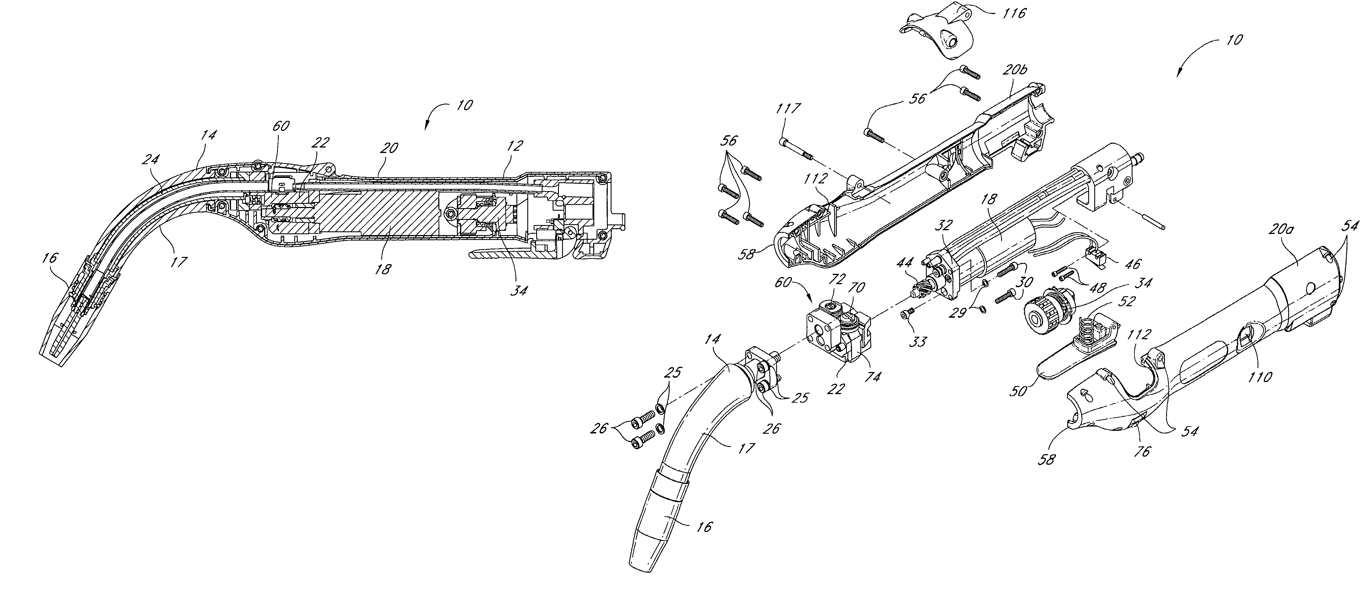
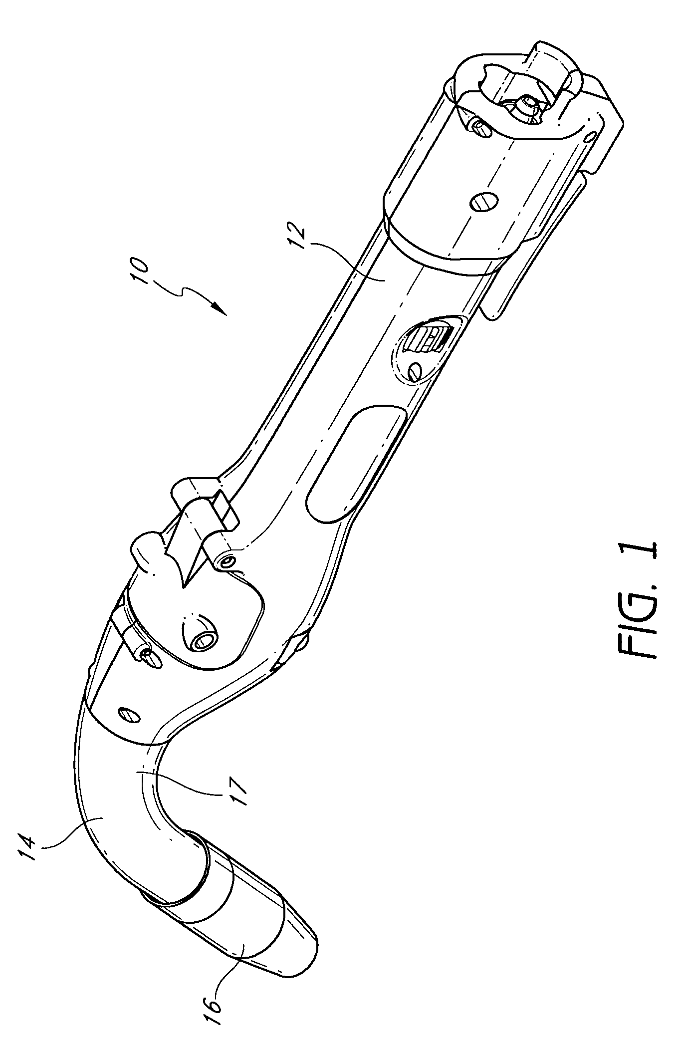
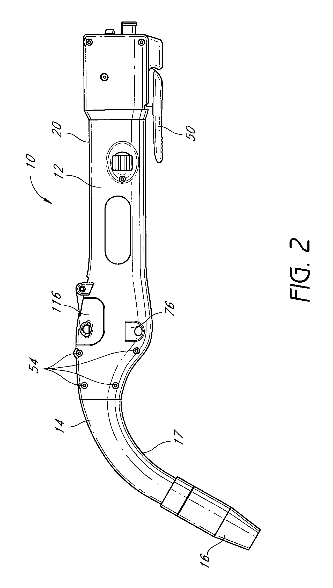
[0035]FIGS. 1 and 2 are a side perspective view and a side view of an illustrated embodiment of a welding gun 10 having certain features and advantages according to the present invention. In the illustrated embodiment, the gun 10 includes a generally tubular handle 12 and a torch portion 14. As best seen in FIG. 3, the gun 10 has a wire-feed motor 18, which is positioned inside the handle 12 generally along the longitudinal axis of the gun 10. The illustrated gun 10, therefore, is an “in-line” welding gun. The handle portion 12 is covered by a substantially rigid, two-piece molded plastic housing 20a, 20b, which is best seen in FIG. 4 and will be described in more detail below.

[0036]With particular reference to FIGS. 3 and 4, the torch portion 14 comprises the torch barrel 24, a variable profile insulating boot 17. The torch barrel 24 is configured to receive a welding tip assembly 16. The welding gun 10 includes a body or block 22, which is preferably made of aluminum. The torch ba...


PUM

PropertyMeasurementUnit
temperaturesaaaaaaaaaa

Abstract

Several aspects of an in-line welding gun are disclosed. In one aspect, the welding gun has a variable profile insulating boot disposed over the torch barrel of the gun. The variable profile insulating boot may include a molded material having varying thickness to provide the desired insulating properties. In another aspect of the welding gun, a speed control mechanism for the motor driving the wire feed assembly is positioned in a recess in the housing such that it reduces the risk of being unintentionally adjusted during operation of the welding gun. In another aspect of the welding gun, the wire feed mechanism features a feeder roller and an idler roller that may be separated without opening the housing of the welding gun. To separate the rollers, the user may depress a portion on the exterior of the housing to press on a pivotable lever on which the idler roller is disposed.

Description

BACKGROUND OF THE INVENTION[0001]1. Field of the Invention[0002]This invention relates generally to a welding gun and, more specifically, to an in-line MIG welding gun.[0003]2. Description of the Related Art[0004]A MIG welding gun generally comprises a handle, a wire feed mechanism, a motor for driving the wire feed mechanism and a torch barrel. The welding gun typically also includes a gas tube and a cooling fluid tube for supplying gas and cooling fluid to the tip of the torch barrel.[0005]There are two general types of welding guns: pistol grip and in-line welding guns. In a pistol grip gun, the motor is located below the wire feed mechanism and lies along an axis that lies generally perpendicular to the longitudinal axis of the gun. In contrast, in an in-line gun, the motor lies along the longitudinal axis of the gun and is positioned generally behind the wire feed mechanism.[0006]Torch barrels may be straight or curved (e.g., “goose necked”) depending upon the type of welding t...

Claims


Application Information

Patent Timeline
Patent Type & Authority Patents(United States)
IPC IPC(8): B23K9/00B23K9/12
CPCB23K9/28
Inventor KENSRUE, MILO M.NGUYEN, TRUNG DINH
Owner M K PRODS
Why Eureka
Try Eureka