Unlock instant, AI-driven research and patent intelligence for your innovation.

Transmission control method of coded video signals and transmission system

a video signal and transmission system technology, applied in the field of transmission system for video signal, can solve the problems of inability to acquire normal compressed data, inability to ensure synchronization, and inability to output at a predetermined frequency

Inactive Publication Date: 2007-07-17
KOKUSA ELECTRIC CO LTD
View PDF10 Cites 11 Cited by
  • Summary
  • Abstract
  • Description
  • Claims
  • Application Information

AI Technical Summary

Benefits of technology

[0028]To solve the problems described above, the present invention provides a practical transmission apparatus that eliminates the necessity for a video switcher equipped with an expensive frame synchronization function by detecting a discontinuous point inside a transmitter, transmitting appropriately the detection result to a receiver, and executing an appropriate processing of an output image on the receiver side before image distortion resulting from the discontinuous point develops. The appropriate processing of the output image may be, for example, a freezing the output image to the latest image, replacing the current image with another normal image, and so on.

Problems solved by technology

Unless these frames keep mutual periodicity (both vertical and horizontal periodicities), normal compressed data cannot be acquired.
The video signals from the plurality of surveillance cameras do not always keep a coincident phase and their synchronization is not ensured.
Therefore, if a plurality of different video signals are switched and one of the video signals is selectively outputted at the timing that is irrelevant to the vertical and horizontal sync signals of the respective video signals, the vertical sync signal or the horizontal sync signal between different video signals so outputted does not keep predetermined periodicity.
Consequently, periodicity of the video signals is distorted.
Therefore, when the discontinuous signal is inputted to the component conversion portion 10, violation occurs in its internal processing portion with the result that the video signal and the sync signal 12 lose periodicity, too.
As a result, collapse and distortion of the image occur eventually in the video monitor 23.
However, because the video switcher equipped with the frame synchronization function is very expensive, the increase of the cost becomes a serious problem particularly in a surveillance system that handle the signals of a large number of cameras.

Method used


Image

  • Transmission control method of coded video signals and transmission system
  • Transmission control method of coded video signals and transmission system
  • Transmission control method of coded video signals and transmission system

Examples


first embodiment

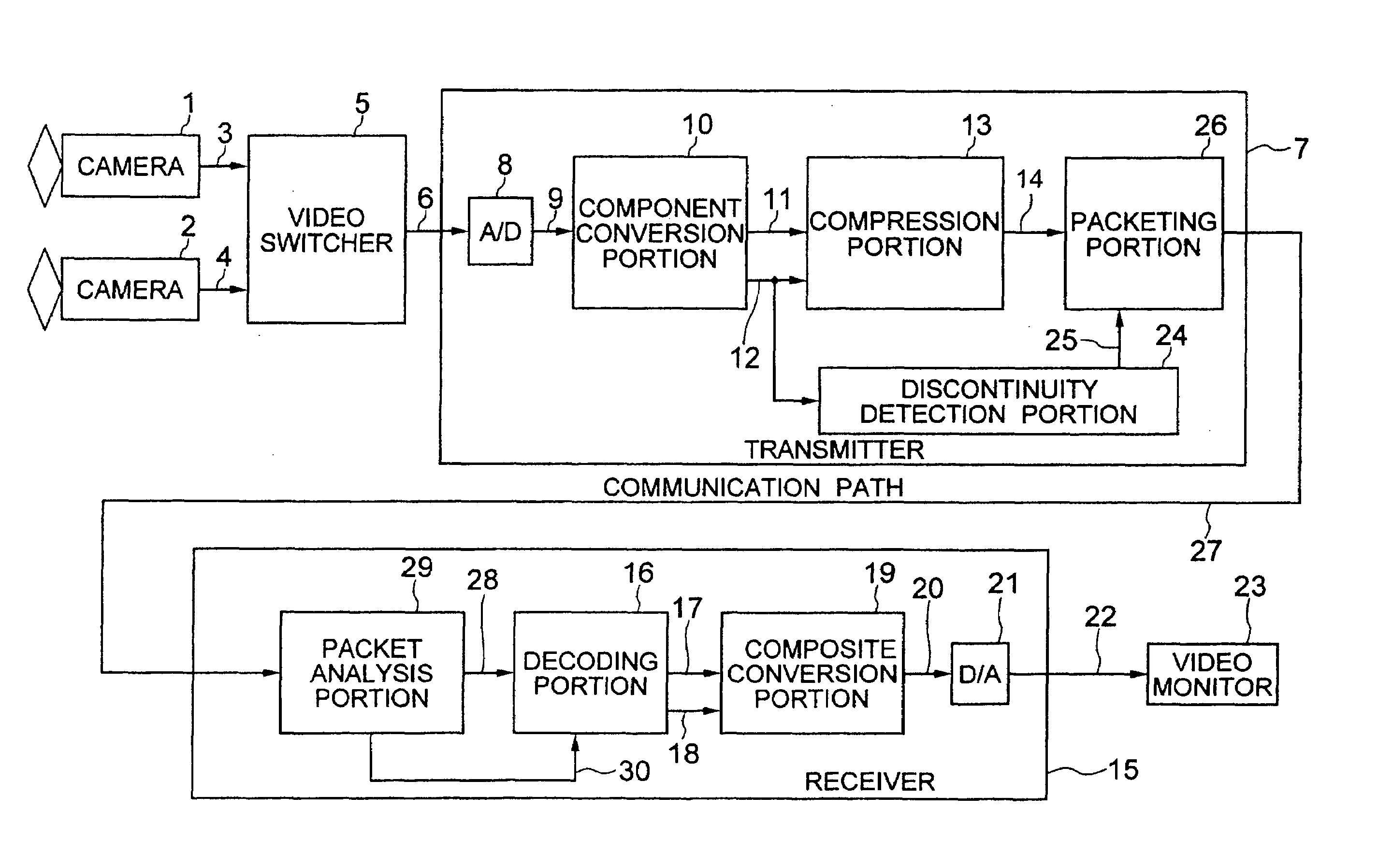
[0049]Hereinafter, the construction of the transmitter according to the present invention will be explained in detail with reference to FIG. 1. In this drawing, like reference numerals will be used to identify like constituent members as in FIG. 3. Reference numerals 1 and 2 denote video cameras for monitoring a monitor object. The embodiment shown in FIG. 1 uses two video cameras, though ten or more video cameras can be used depending on the system configuration.

[0050]The output signals 3 and 4 of these video cameras are inputted to a video switcher 5 and are automatically switched in a predetermined cycle (e.g. several seconds). The selected signals are inputted as the video signals 6 to a transmitter 7.

[0051]In this transmitter 7, the video signal 6 is inputted to an A / D converter 8 and is converted to a digital composite signal 9.

[0052]The digital composite signal 9 is inputted to a component conversion portion 10 and is outputted as a video signal 11, that is separated into a l...

second embodiment

[0113]FIG. 7 shows the construction of this The difference of this embodiment from the embodiment shown in FIG. 1 is that the reset signal 33 from the discontinuity detection portion 32 is given to the compression portion 31, too.

[0114]Next, the operation of the second embodiment will be explained with reference to FIG. 8. The compression portion 31, too, is reset simultaneously by the reset signal 33 from the discontinuity detection portion 32. In consequence, the stream 14 from the compression portion 31 enters the non-output state (reset state).

[0115]Resetting by the reset signal 33 is released when periodicity of the sync signal 12 is recovered. As resetting is released, the compression portion 31 starts processing. Since a certain time (about 33 msec) is necessary before the stream 14 as the compression-processing result is outputted. In the interim, the compression portion 31 quite naturally remains under the non-output state.

[0116]On the other hand, the packeting portion 26 ...


PUM


Abstract

A system for transmitting coded digital video signals in a packet form through a signal line and a method of controlling the system. A transmission portion converts the digital video signals to a signal stream as a sequence of a plurality of packets each containing a predetermined sync code and a payload, and transmitting the signal stream. In case a fail of periodicity of the video signals is detected, a signal stream containing a packet into which a predetermined dummy signal not being the sync code is inserted into a position of sync code in a packet to be transmitted at that time and is transmitted. When receiving no sync code at a predetermined portion in the received packet, a reception portion executes an image reproduction process on the basis of the video signal data not depending on the packet containing the dummy signal and is so received.

Description

BACKGROUND OF THE INVENTION[0001]This invention relates to a system for transmitting video signals and its control method. When coded digital video signals are transmitted, this system ensures images devoid of image distortion on the reception side even when consecutiveness of the signals is lost.[0002]MPEG2 compression system of the global standard has gained a wide application at present for compressing and transmitting video signals.[0003]The MPEG2 compression system or an equivalent system is based on the premise that input video signals that are compressed are consecutive signals keeping periodicity.[0004]For, compressed image data of one frame are generated in the compression process by using data of a plurality of frames having mutually different time. Unless these frames keep mutual periodicity (both vertical and horizontal periodicities), normal compressed data cannot be acquired.[0005]FIG. 2 of the accompanying drawings shows schematically the outline of input analog video...

Claims


Application Information

Patent Timeline
IPC IPC(8): H04N7/12
CPCH04L29/06027H04N21/2187H04N21/242H04L65/602H04L65/604H04L65/607H04N7/104H04L65/764H04L65/762H04L65/70H04L65/1101
Inventor OHNAMI, YUICHI
Owner KOKUSA ELECTRIC CO LTD