Low power and high linearity receivers with reactively biased front ends

a receiver and reactive bias technology, applied in the direction of pulse technique, dc level restoring means or bias distort correction, low noise amplifier, etc., can solve the problems of cross talk or intermodulation between the two signals, the inability of every electronic circuit to effectively handle inputs larger, so as to reduce linearity, increase intermodulation susceptibility, and reduce power consumption

Inactive Publication Date: 2007-07-24
SONY CORP +1
View PDF22 Cites 18 Cited by
  • Summary
  • Abstract
  • Description
  • Claims
  • Application Information

AI Technical Summary

Benefits of technology

[0016]Thus, there is a need for amplifiers, buffers and other front-end circuits for receivers in which power consumption can be decreased in favorable signal environments without reducing linearity or increasing intermodulation susceptibility in adverse signal environments. This need can be met by means of reactively adjusting the bias level at which such circuits operate, i.e. by increasing its bias level in reaction to adverse or strong signal environments so as to allow it to operate using less power in weaker or typical signal environments.

Problems solved by technology

Every electronic circuit is unable to product outputs larger than some limit.
Every electronic circuit is unable to effectively handle inputs larger than some limit or smaller than some other limit.
If a desired signal and a jamming source at different frequencies are present at the same time (which is typical of the operating environment for radio receivers), then this frequency shift results in cross talk or intermodulation between the two signals.
Unfortunately, the larger the bias of an amplifier, the more power it consumes.
Thus, there is a tradeoff between an amplifier's power consumption on the one hand and its range of linearity and susceptibility to intermodulation on the other hand.
However, prior art techniques for doing this also reduce the receiver's linear range and thus increase its susceptibility to intermodulation from jamming sources.

Method used


Image

  • Low power and high linearity receivers with reactively biased front ends
  • Low power and high linearity receivers with reactively biased front ends
  • Low power and high linearity receivers with reactively biased front ends

Examples


Embodiment Construction

[0034]Disclosed herein are various alternative embodiments of and alternative designs for the invention. The invention, however, should not be taken as being limited to the embodiments and alternatives described. One skilled in the art will recognize still other alternative embodiments and designs, as well as various changes in form and detail. These may be employed while practicing the invention without departing from its principles, spirit or scope.

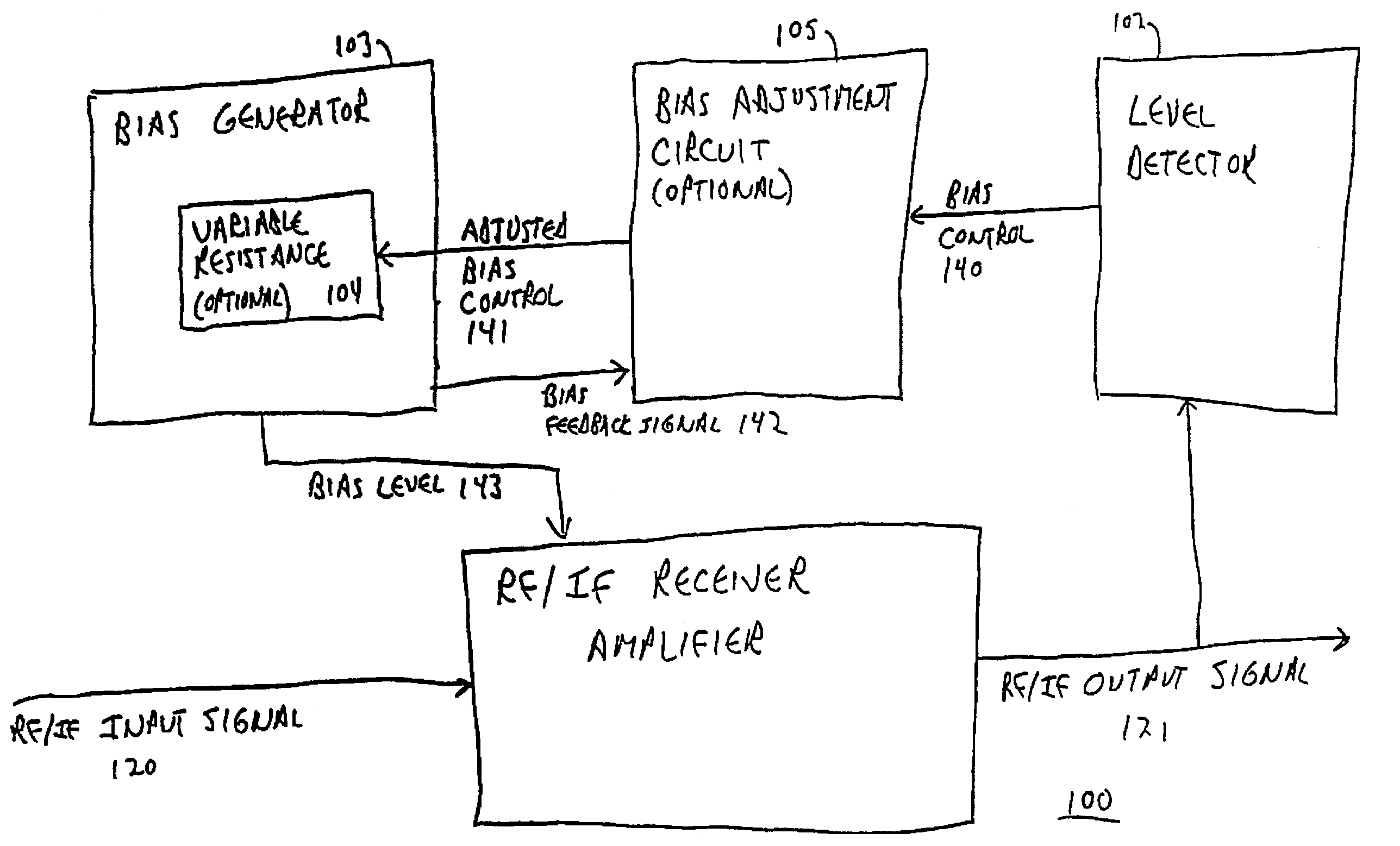
[0035]FIG. 1 is a functional block diagram of receiver amplifier 100 according to one embodiment of the invention. This amplifier has reactive biasing, i.e. it adjusts its bias level in reaction to the signal strength with which it is currently operating.

[0036]RF / IF receiver amplifier 101 amplifies input signal 120 into output signal 121. The bias of amplifier 101 is set by bias level 143, which is produced by bias generator 103.

[0037]RF / IF receiver amplifier 101 can be any type of linear amplifier with characteristics suitable for radi...


PUM


Abstract

A radio frequency receiver includes an amplifier and a detector that produces a bias control signal based on a signal environment. A bias level of the amplifier is set according to the bias control signal. Bias levels other receiver circuits may have similarly adjusted bias levels, including buffers, IF oscillators, mixers, and converters. The invention can be used to increase range of linearity, intermodulation immunity and reduce power consumption by reducing the bias level under typical conditions and relying on the bias control to increase bias levels under adverse signal conditions. The invention has advantages where power is at a premium, particularly when a device is in standby mode, including mobile, portable and hand held pagers and wireless telephones and Internet connections. If standby mode operation in non-maximum signal environments dominates the usage of the receiver, then the invention can substantially increase battery life.

Description

CROSS-REFERENCE TO RELATED APPLICATION[0001]This application is a continuation of U.S. patent application Ser. No.: 09 / 753,123, filed Dec. 29, 2000 now U.S. Pat. No. 6,625,238, which is a continuation-in-part of U.S. patent application Ser. No. 09 / 538,606, filed Mar. 29, 2000 now U.S. Pat. No. 6,782,062, wherein U.S. patent application Ser. No. 09 / 753,123 is hereby fully incorporated herein by reference.FIELD OF THE INVENTION[0002]The invention relates to the design of electronic receivers. In particular, it relates to achieving a low power and high linearity receiver by means of reactively adjusting the bias level used by its front-end circuits, such as amplifiers, buffers and mixers.RELATED APPLICATIONS[0003]This application is a continuation in part of U.S. patent application Ser. No. 09 / 539,165, filed Mar. 29, 2000, entitled “Low Power and High Linearity Receivers with Reactively Biased Front Ends” by the same inventor and assigned to the same assignee.BACKGROUND OF THE INVENTIO...

Claims


Application Information

Patent Timeline
Patent Type & Authority Patents(United States)
IPC IPC(8): H04L27/08H03F1/02H03F3/193H04B1/10
CPCH03F1/0272H03F3/1935H04B1/109H03F2200/294H03F2200/372H03F2203/7239
Inventor WIECK, CHRISTOPHER P.
Owner SONY CORP
Why Eureka
Try Eureka