Method and device for the robot-controlled cutting of workpieces to be assembled by means of laser radiation

a technology of laser radiation and robot control, which is applied in the direction of programme control, instruments, geometries, etc., can solve the problems of unsatisfactory processing width to be achieved of approximately 50 mm, control correction, and inability to welded the radius of less than 50 mm using the known method, and achieve the effect of significant precision, significant beam quality, and significant increase of the manipulation range of the robo

Inactive Publication Date: 2007-07-24
THYSSEN LASER TECHN +1
View PDF10 Cites 20 Cited by
  • Summary
  • Abstract
  • Description
  • Claims
  • Application Information

AI Technical Summary

Benefits of technology

[0030]A compact and rigid configuration of the device in the area of the robot hand is achieved in particular when a distance adjusting range of the focal point to a processing point is +/−1.5 mm in a parallelogram plane. Under these conditions, it is possible in particular to employ very precise encoders for the adjustment of optical components as a fast axis for adjusting the processing point.
[0031]Moreover, it can be advantageous that for generating the laser radiation a laser having a beam quality of k 0.35 is present. The high beam quality ensures a narrow shape of the laser beam in the focal area with different spacings from the first workpiece in the incidence direction, this allows cutting without having to carry out a spacing correction, for example, by adjusting an optical element of a processing optics in the incidence direction.
[0032]In order to be able to carry out distance measurements in the incidence direction, the device can be configured such that a laser measuring beam extending coaxially to the laser beam and hav

Problems solved by technology

Moreover, radii of less than 50 mm cannot be welded with the known method because the robot control correction is too slow.
The processing width to be achiev

Method used


Image

  • Method and device for the robot-controlled cutting of workpieces to be assembled by means of laser radiation
  • Method and device for the robot-controlled cutting of workpieces to be assembled by means of laser radiation
  • Method and device for the robot-controlled cutting of workpieces to be assembled by means of laser radiation

Examples


Embodiment Construction

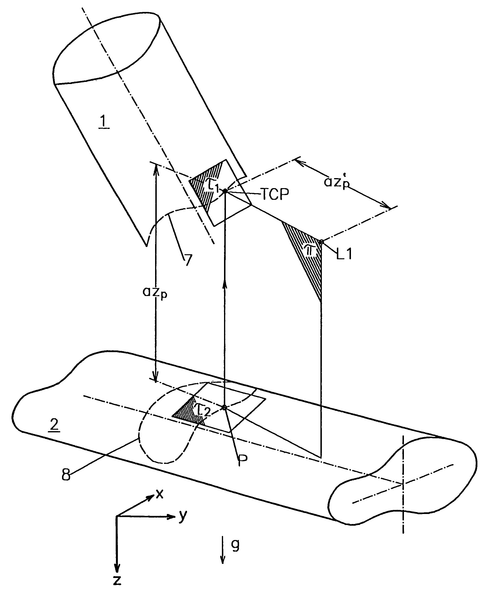
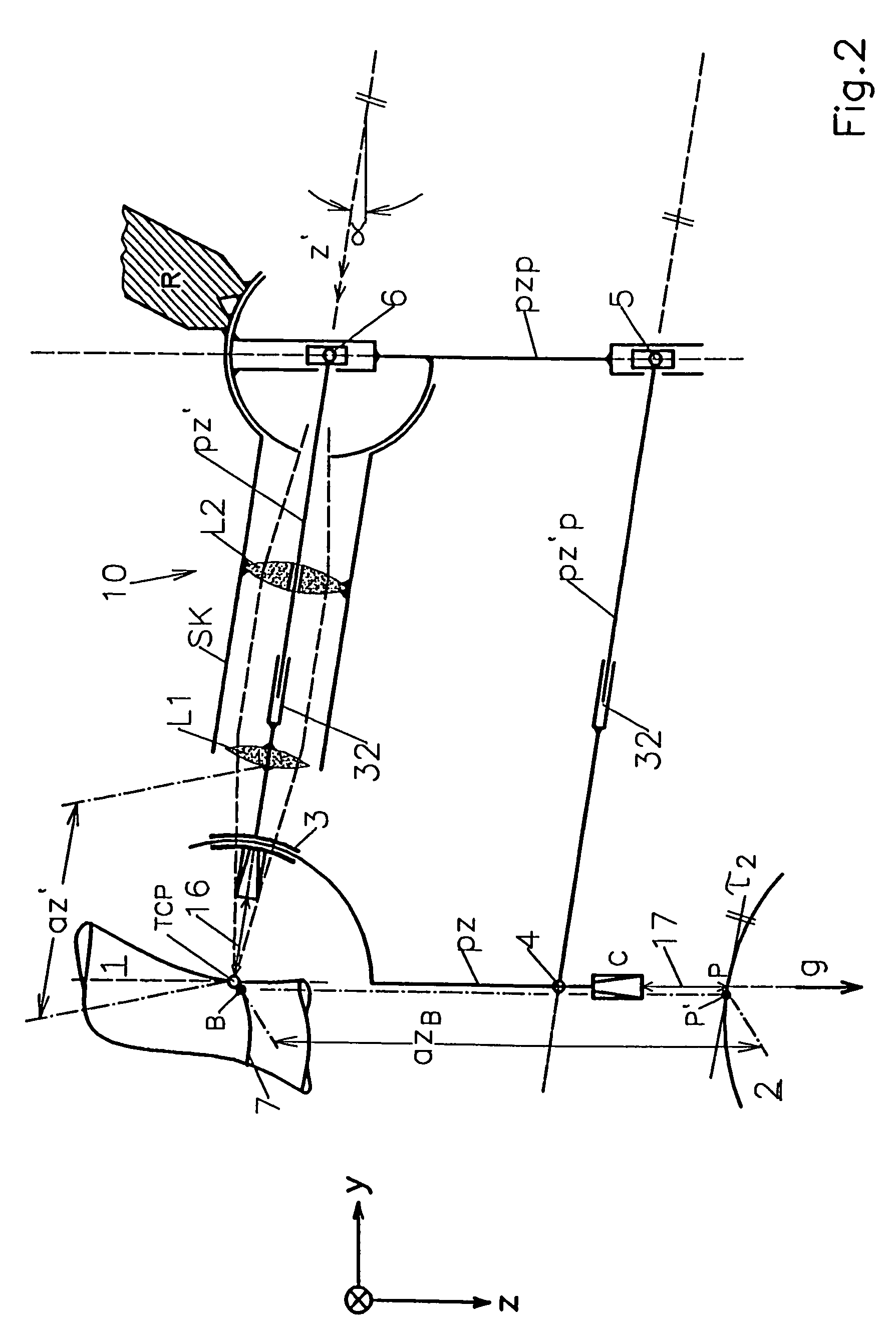
[0040]In order to be able to perform robot-controlled cutting of workpieces, manipulation devices are required that are embodied as robots, for example, buckling arm robots. Such buckling arm robots are generally known and can be configured, for example, as a 6-axis robot. For example, a base axis is provided which is configured as an axis of rotation and is fastened at or on a support surface. A pivot axis can be connected to such an axis of rotation, i.e., a robot arm having at its other end an additional pivot axis for a rotary arm that forms a fourth robot axis and is provided at its end facing the workpiece with a robot hand carrying a machining head. The robot hand has a hand axis as a fifth axis of the robot whose components are schematically illustrated in FIG. 4. The fifth axis of the robot supports a further axis, the sixth axis, as indicated generally in FIG. 4 at 10. The fifth axis together with mirrors 28 and 29 is illustrated rotated about the sixth axis and rotated by...


PUM

PropertyMeasurementUnit
Angleaaaaaaaaaa
Distanceaaaaaaaaaa
Frequencyaaaaaaaaaa

Abstract

In a method for robot-controlled cutting of workpieces to be joined by laser radiation, a first workpiece is arranged in vicinity of a second workpiece in a first position. A laser is focused onto the first workpiece. A contour of the first workpiece is cut with the laser beam; this contour is to be assembled and joined with the second workpiece. During cutting, a first spacing of a focal point of the laser beam from the second workpiece is repeatedly determined in a distance direction that is identically oriented during cutting and is adjusted to a direction of assembling the first and second workpieces. During cutting, a second spacing of a processing point of the laser beam from the second workpiece is maintained at a constant value.

Description

BACKGROUND OF THE INVENTION[0001]The invention relates to a method for robot-controlled cutting of workpieces to be joined by means of laser radiation that is being focused onto a first workpiece whose cut contour is assembled and joined with a second workpiece.[0002]Such a method is known in general. It is carried out conventionally with buckling arm robots that, based on their low adjusting frequency of approximately 10 Hz for all axes, have significant impression for cutting and welding. In addition, there are impressions as a result of the mechanical manufacture of the robot parts, of the employed encoders, and as a result of the machine-internal coordinate system that deviates from an ideal coordinate system. Moreover, dynamically caused impressions of the focal point position are present. Depending on the gear configuration and amount of teach points, a path repetition precision of only approximately + / −0.1 to + / −0.4 mm in any of the three coordinate directions is achieved for...

Claims


Application Information

Patent Timeline
IPC IPC(8): G06F19/00B23K26/02B23K26/046B23K26/08B23K26/10B23Q27/00
CPCB23K26/046B23K26/0884B23Q27/00
Inventor NEUMANN, GUNTERBEHR, FRIEDRICHFISCHER, AXELKROTH, EBERHARDSEILER, STEFANSOM, FRANZMAISCH, ROLF P.ZESCH, WOLFGANG
Owner THYSSEN LASER TECHN
Why Eureka
Try Eureka