Method of manufacturing magnetic head

a manufacturing method and magnetic head technology, applied in the field of manufacturing a magnetic head, can solve the problem of not being able to properly control the thickness of the gap layer b, and achieve the effect of improving the control of the thickness of the gap layer and the shape of the gap layer

Inactive Publication Date: 2007-07-31
ALPS ALPINE CO LTD
View PDF6 Cites 9 Cited by
  • Summary
  • Abstract
  • Description
  • Claims
  • Application Information

AI Technical Summary

Benefits of technology

[0012]The present invention has been finalized in view of the drawbacks inherent in the conventional magnetic head, and it is an object of the present invention to provide a method of manufacturing a magnetic head which is capable of improving thickness controllability of a gap layer.
[0014]According to this aspect, the coil base layer is formed on the contact layer. In this case, at least a surface layer of the coil base layer is formed of one or two or more alloys selected from Au, Ru, and Rh. Thereby, the surface of the coil base layer is not oxidized due to the air exposure, so that the contact layer is not oxidized. As such, the contact layer is properly protected by the coil base layer. Therefore, unlike the related art, since the etching process for removing the oxide layer is not necessary before proceeding to the step (d), it is possible to improve the film thickness control and shape control of the gap layer without cutting the gap layer by the etching process, and it is possible to restrict the gap depth to a predetermined value. In particular, these effects can be achieved without increasing the number of processes, as compared with the related art, and since the etching process is not necessary, the number of the processes can be reduced as compared to the related art. This is because the coil base layer functions as a base when the coil layer is formed and functions as a protective layer for preventing the surface of the contact layer from oxidizing.
[0015]Preferably, during the step (b), a portion of the coil base layer that is not covered with the coil layer is removed in a state in which the coil base layer formed on the contact layer is protected after forming the coil layer. Thereby, the coil base layer can remain on the contact layer. In addition, by removing the unnecessary coil base layer, the coil base layer remaining below the coil layer can be electrically separated from the coil base layer remaining on the contact layer.
[0017]Preferably, the conductive layer in the step (e) is formed of the same material as the second magnetic layer, and the forming of the second magnetic layer in the step (d) and the forming of the conducive layer in the step (e) are simultaneously performed. Thereby, the manufacturing process can be simplified.
[0019]According to the embodiment of the invention, the coil base layer having at least a surface layer formed of one or two or more alloys selected from Au, Ru, and Rh is formed on the contact layer. Thereby, the surface of the coil base layer is not oxidized due to the air exposure, so that the contact layer is not oxidized. As such, the contact layer is properly protected by the coil base layer. Therefore, unlike the related art, since the etching process for removing the oxide layer is not necessary, it is possible to improve control of the film thickness and shape of the gap layer without cutting the gap layer by the etching process as compared with the related art, and it is possible to restrict the gap depth to a predetermined value.

Problems solved by technology

As such, in the conventional method of manufacturing the magnetic head, since deviation may occur in the thickness of the gap layer 9, it is not possible to properly control the thickness of the gap layer 9.

Method used


Image

  • Method of manufacturing magnetic head
  • Method of manufacturing magnetic head
  • Method of manufacturing magnetic head

Examples


Embodiment Construction

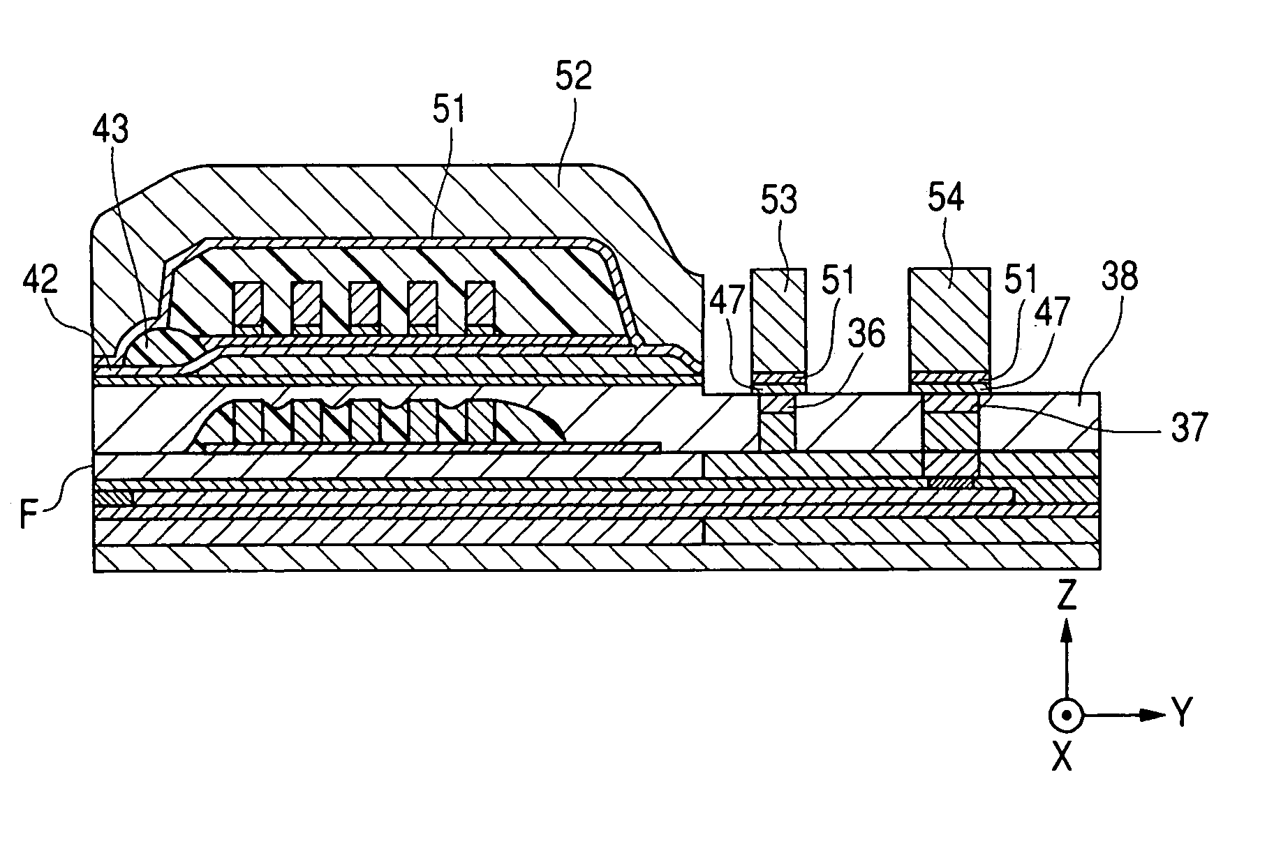
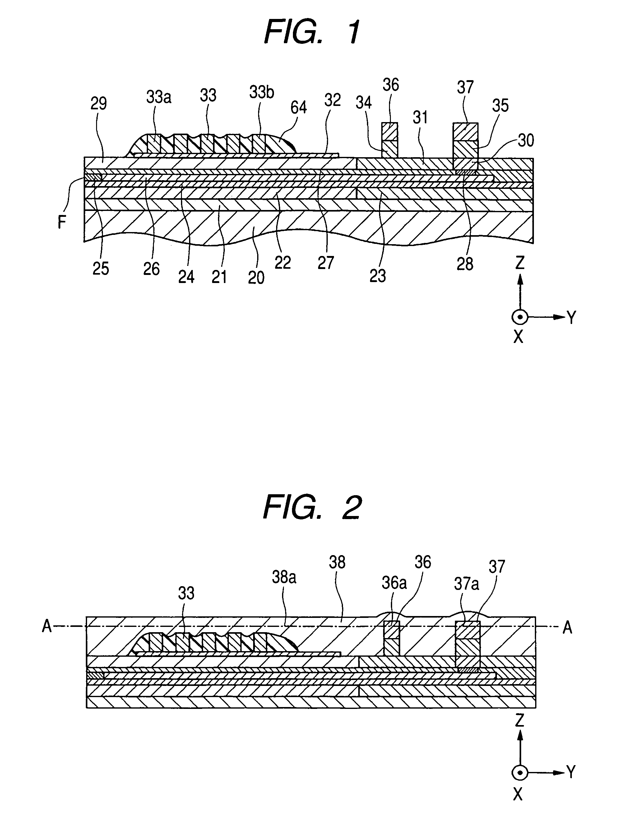
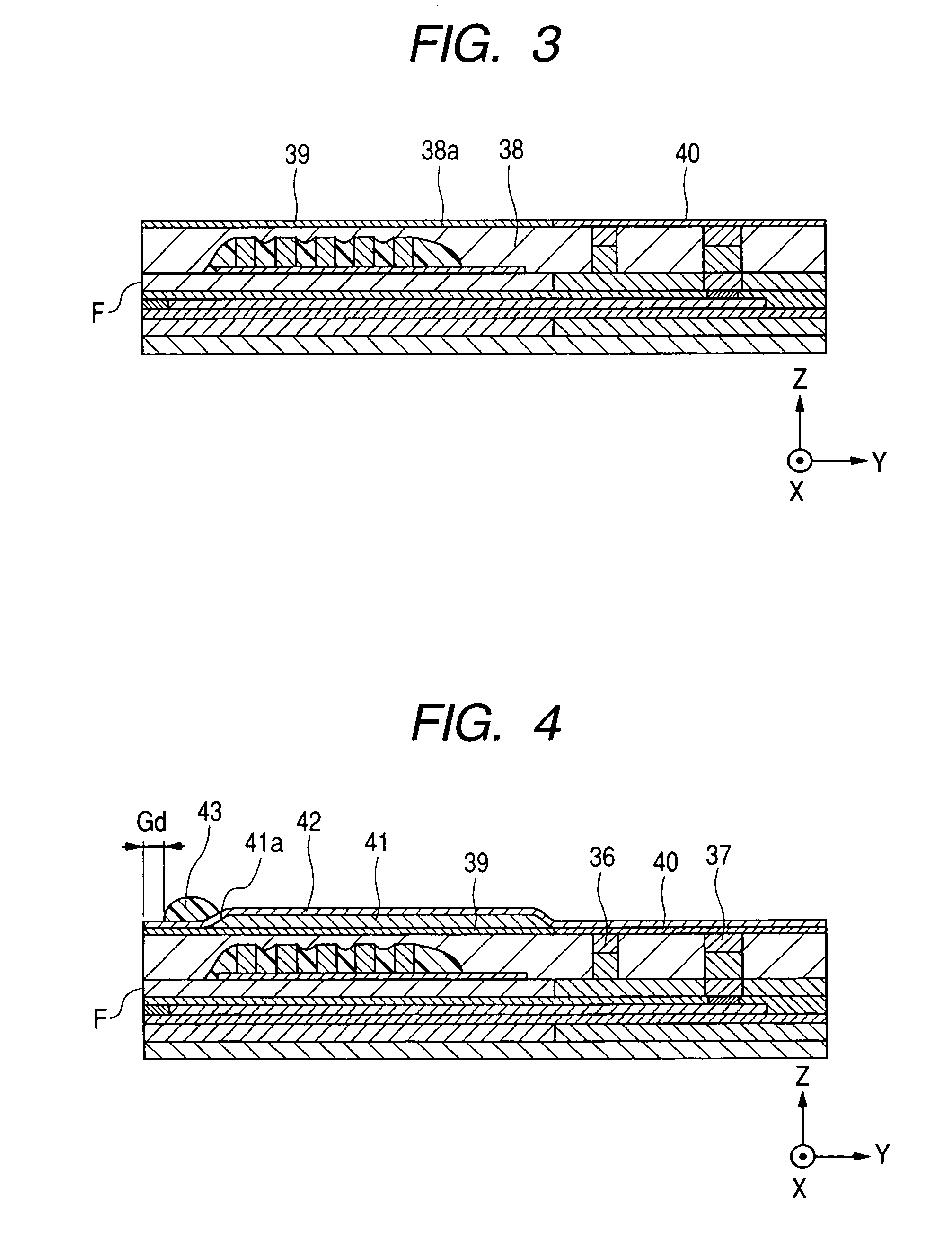
[0037]FIGS. 1 to 12 are partial longitudinal cross-sectional views of a magnetic head which are diagrams illustrating processes of a method of manufacturing the magnetic head according to an embodiment of the invention.

[0038]Hereinafter, in the respective drawings, an X direction is referred to as a track widthwise direction. The track widthwise direction is a direction which is orthogonal to each film thicknesswise direction and heightwise direction ((element heightwise direction). A direction which is perpendicular to a surface F facing a recording medium (a surface parallel to an X-Z plane) and spaced apart from the surface F facing the recording medium)). In addition, a Y direction in the drawings is the heightwise direction, and a Z direction in the drawings is a film thicknesswise direction.

[0039]In FIG. 1, reference numeral 20 indicates a slider. The slider 20 is formed of a non-magnetic material, such as Al2O3.TiC or the like. As shown in FIG. 1, an insulating material layer...


PUM

PropertyMeasurementUnit
magnetic fieldaaaaaaaaaa
conductiveaaaaaaaaaa
magneticaaaaaaaaaa

Abstract

A method of manufacturing a magnetic head is provided which can improve controlling a thickness of a gap layer. A coil base layer having at least a surface layer formed of one or two or more alloys selected from Au, Ru, and Rh is formed on a contact layer. Thereby, since a surface of the coil base layer is not oxidized due to air exposure, the contact layer is not oxidized. As such, the coil base layer protects the contact layer, so that it is not necessary to perform an etching process for removing an oxide layer, as in the related art. Therefore, it is possible to further improve controlling a thickness of a gap layer without cutting the gap layer by the etching process, as compared with the related art.

Description

BACKGROUND OF THE INVENTION[0001]1. Field of the Invention[0002]The present invention relates to a method of manufacturing a magnetic head which is capable of improving controlling a thickness of a gap layer.[0003]2. Description of the Related Art[0004]Generally, an inductive head for recording a magnetic signal on a recording medium has a structure in which it includes a first magnetic layer and a second magnetic layer that are opposite to each other in a film thicknesswise direction at a surface facing the recording medium with a gap layer interposed therebetween, and a coil layer that is provided between the first magnetic layer and the second magnetic layer at a location farther than the facing surface in a heightwise direction.[0005]FIG. 15 is a diagram illustrating one process of a method of manufacturing a conventional perpendicular magnetic recording head. In addition, FIG. 15 is a partial longitudinal cross-sectional view of the conventional perpendicular magnetic recording...

Claims


Application Information

Patent Timeline
Patent Type & Authority Patents(United States)
IPC IPC(8): G11B5/127H04R31/00
CPCG11B5/1278G11B5/3116G11B5/3163Y10T29/49044Y10T29/49027Y10T29/49048Y10T29/49073Y10T29/49037Y10T29/49046Y10T29/49041Y10T29/49052
Inventor KOBAYASHI, KIYOSHI
Owner ALPS ALPINE CO LTD
Why Eureka
Try Eureka