System and process for post alignment polarization extinction ratio compensation in semiconductor laser system

a technology of polarization extinction ratio and semiconductor laser system, which is applied in the field of system and process for post alignment polarization extinction ratio compensation in semiconductor laser system, can solve the problems of mechanical stress placed on the fiber, per ratio of optical system, and not the case, and achieve the effect of maximizing coupling efficiency

Inactive Publication Date: 2007-07-31
EXCELITAS TECH
View PDF11 Cites 7 Cited by
  • Summary
  • Abstract
  • Description
  • Claims
  • Application Information

AI Technical Summary

Benefits of technology

[0016]In one embodiment, the manufacturing process further comprises a step of aligning the endface to the semiconductor chip. In one implementation, an active alignment process is used in which the semiconductor chip is energized and the magnitude of light coupled into the optical fiber monitored. The endface is then moved relative to the semiconductor chip to maximize the coupling efficiency.

Problems solved by technology

Problems arise, however, when this fiber is integrated into larger optical systems.
Many times, however, this is not the case, especially in systems that are manufactured for commercial applications.
The degradation in the PER ratio of the optical system results from mechanical stresses placed on the fiber during the manufacture of the systems.
These asymmetric stress fields lead to distortions in the stress-induced birefringent medium of the fiber.
This results in coupling between the two polarization modes of the PM fiber that consequently degrade the PER of the system from that expected from the separate components.

Method used


Image

  • System and process for post alignment polarization extinction ratio compensation in semiconductor laser system
  • System and process for post alignment polarization extinction ratio compensation in semiconductor laser system
  • System and process for post alignment polarization extinction ratio compensation in semiconductor laser system

Examples


Embodiment Construction

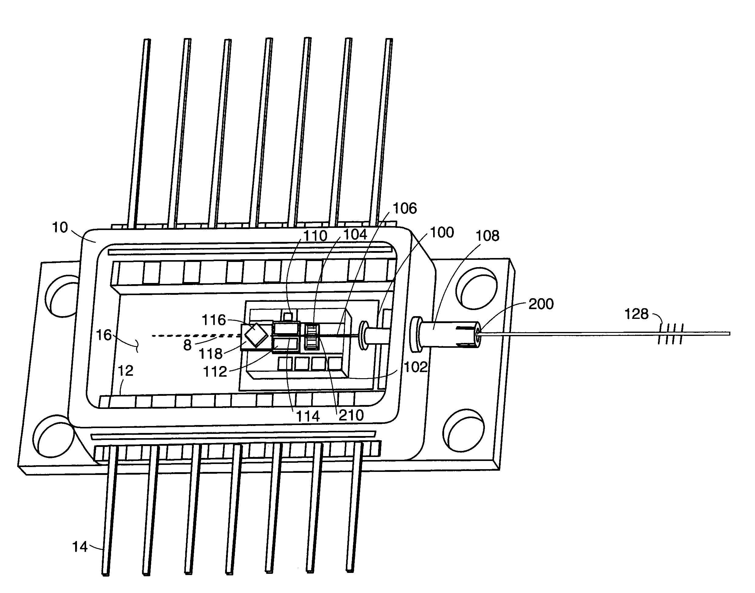
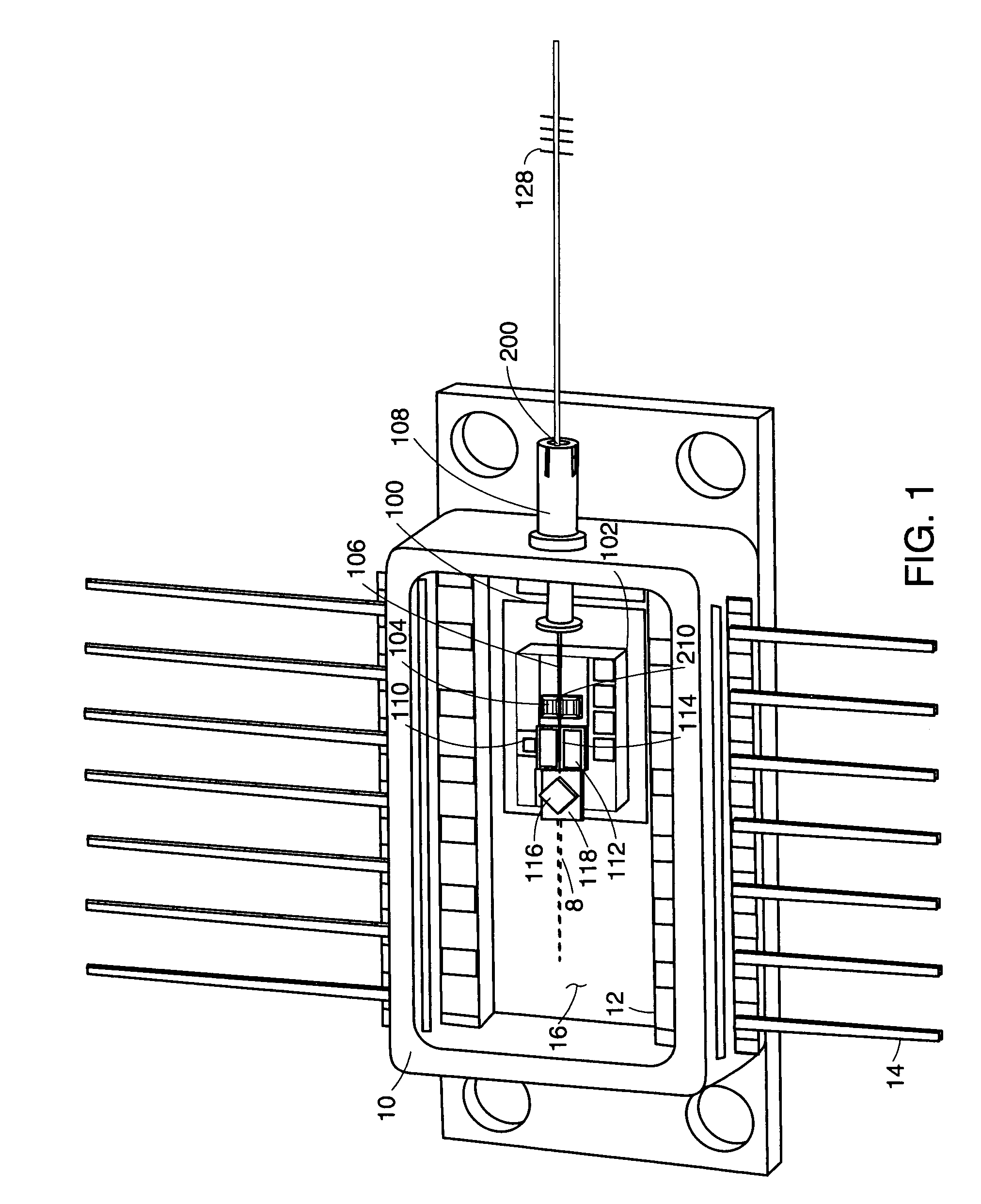
[0028]FIG. 1 shows a semiconductor laser system, which has been constructed according to the principles of the present invention.

[0029]Specifically, the system comprises a package 10. In the illustrated example, a butterfly package is used in which leads 14 extend laterally from the package. In other implementations, the invention can also be applied to DIP packages where the leads 14 extend orthogonally from the floor 12 of the package 10.

[0030]In the illustrated cooled laser system, a thermo-electric cooler 100 is installed on the floor 16 of the package 10. These coolers are typically driven in response to the temperature within the package, detected by thermistor 110 for example, to maintain a temperature-stable operating environment for the semiconductor laser chip.

[0031]A bench or submount 102 is secured to the cooler 100. In the preferred embodiment, the bench is constructed from a mechanically and temperature stable substance, such as aluminum nitride, silicon, silicon-metal...


PUM


Abstract

A system and process for tuning the PER of an electronic system during and/or after its manufacture includes fixtures that allow for the axial rotation of the polarization-maintaining optical fiber relative to the optical system after the optical fiber has been installed in the system. The degradation in the PER ratio of the optical system results from mechanical stresses placed on the fiber during the manufacture of the systems. For example, in the case of optical pump manufacturing, the semiconductor laser is installed on a submount. The PM fiber enters a package through a fiber feedthrough in a ferrule and then is secured down onto the submount, such that the endface of the pigtail is held in proximity to the exit facet of the semiconductor laser. In such systems, highly robust fixturing processes are used, typically such as solder bonding, in which the fiber is metallized and solder bonded either directly or indirectly to the submount. Further, solder is typically applied to seal the ferrule around the fiber since these packages must be hermetically sealed to provide for the long-term stable operation. The solder bonding processes can create asymmetries in the residual stress fields applied around the circumference of the fiber after the solder has cooled. These asymmetric stress fields lead to distortions in the stress-induced birefringent medium of the fiber. This results in coupling between the two polarization modes of the PM fiber, and consequently the degradation of the PER of the system from that expected from the separate components, for which the present invention can compensate.

Description

BACKGROUND OF THE INVENTION[0001]Polarization control is required in many different types of fiber optic applications. The typical modality for obtaining this control is polarization-preserving or polarization-maintaining optical fiber. Standard single-mode optical fiber supports two orthogonal eigenmodes or polarizations. In nominally circular fibers, the polarization modes are degenerate with an identical propagation constant and group phase velocity.[0002]Polarization-maintaining (PM) fiber is sometimes referred to as high birefringence single-mode fiber. PM fiber utilizes a stress-induced birefringence mechanism to achieve high levels of birefringence such that polarized light travels at different speeds along the orthogonal polarized axes of the fiber. Typically, these fibers embed a stress-applying region in the cladding area of the fiber. When placed symmetrically about the core, it gives a fiber cross-section two distinct axes of symmetry. These cross-sections range from ell...

Claims


Application Information

Patent Timeline
Patent Type & Authority Patents(United States)
IPC IPC(8): G02B6/36H01S3/10G02B6/42
CPCG02B6/4201G02B6/4216G02B6/4226G02B6/4203G02B6/4227G02B6/4238G02B6/4248G02B6/4271
Inventor KORN, JEFFREY A.WHITNEY, PETER S.FLANDERS, DALE C.
Owner EXCELITAS TECH
Why Eureka
Try Eureka