
Method and apparatus for stabilizing the temperature of dielectric-based filters

a technology of dielectric filters and temperature stabilization, applied in the direction of waveguide devices, resonators, basic electric elements, etc., can solve the problems of adverse frequency shift, large limitation high temperature resistance of current dielectric materials, so as to limit the effect of dielectric constant, reduce the effect of heat dissipation and prolong the li

Inactive Publication Date: 2007-07-31
ANTONE WIRELESS CORP
View PDF5 Cites 6 Cited by
  • Summary
  • Abstract
  • Description
  • Claims
  • Application Information

AI Technical Summary

Benefits of technology

"The invention is a device and method for stabilizing the temperature of filters and resonators made of dielectric materials used in filters and resonators. The device uses a temperature maintenance device with heating and cooling capabilities to maintain the temperature of the filters within a small range, preferably around room temperature. The device can also include other components of the transmit / receiver chain, such as low noise amplifiers and A-D converters, which can be maintained at or near room temperature to improve their lifespan."

Problems solved by technology

Unfortunately, there are a number of limitations with current dielectric-based resonators.
First, current dielectric materials tend to be very sensitive to temperature changes.
As the temperature of the dielectric material changes, the dielectric constant and dimensions of the material will also change, thereby causing an adverse shift in frequency.
Second, current filters which are formed from dielectric materials tend to be large and bulky due the large volume of dielectric material needed to form the individual filters.
Both of these limitations result in the added cost associated with dielectric filters relative to metal cavity filters
Unfortunately, this leads to a lowering of the average dielectric constant of the dielectric material.
Consequently, a large volume of material is needed in these solutions.
Moreover these solutions produce filters with increased overall loss (lower Q values).
There also is the disadvantage that actual construction of the filter requires bimetals / multiple metals to compensate for the different thermal properties between the housing (or stage) and the dielectric component.

Method used


Image

  • Method and apparatus for stabilizing the temperature of dielectric-based filters
  • Method and apparatus for stabilizing the temperature of dielectric-based filters
  • Method and apparatus for stabilizing the temperature of dielectric-based filters

Examples


Embodiment Construction

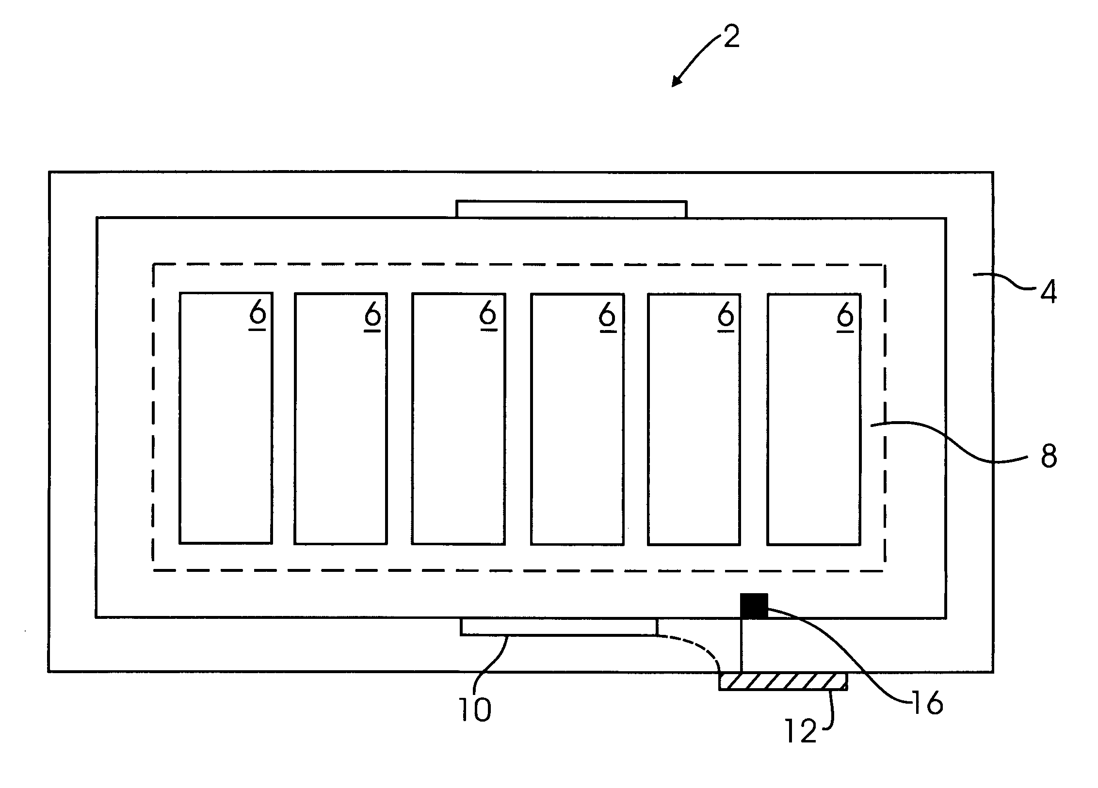
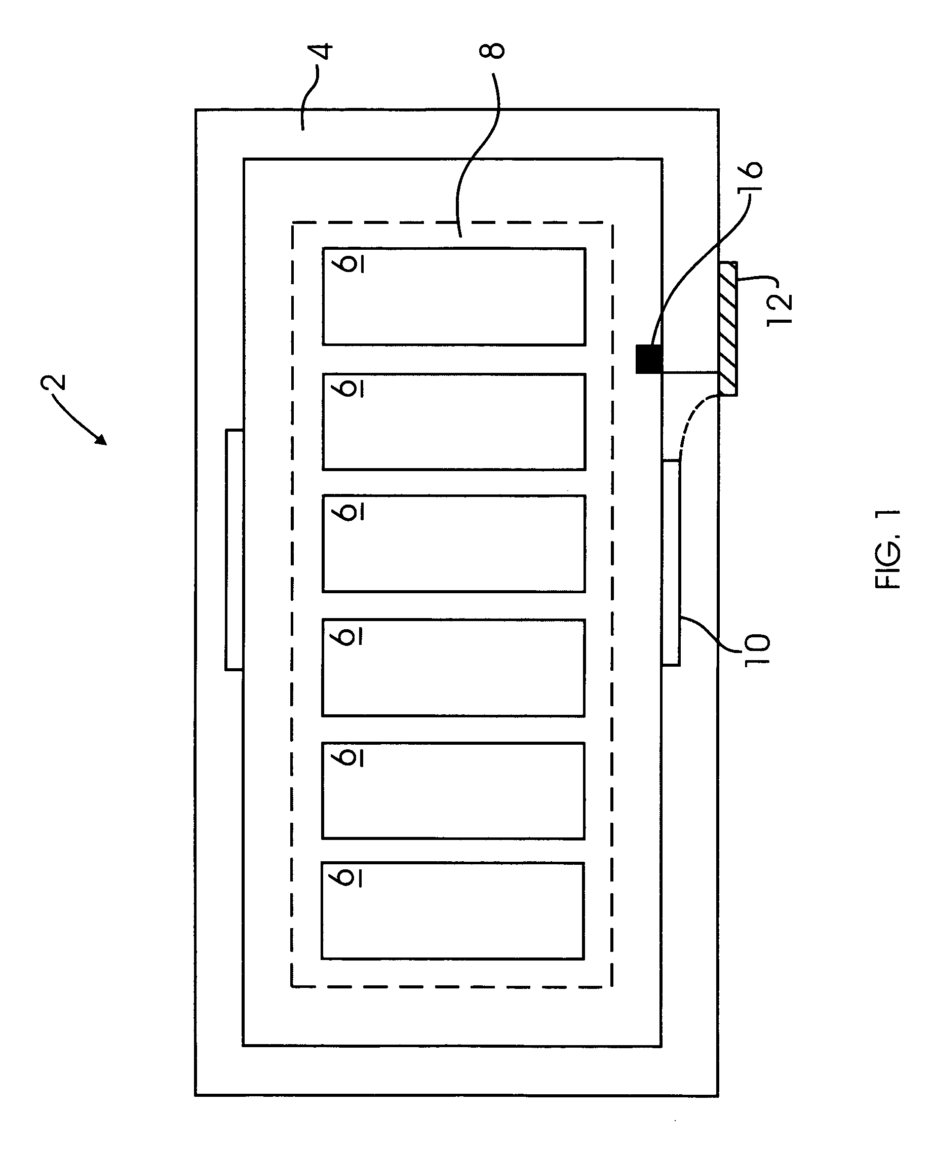
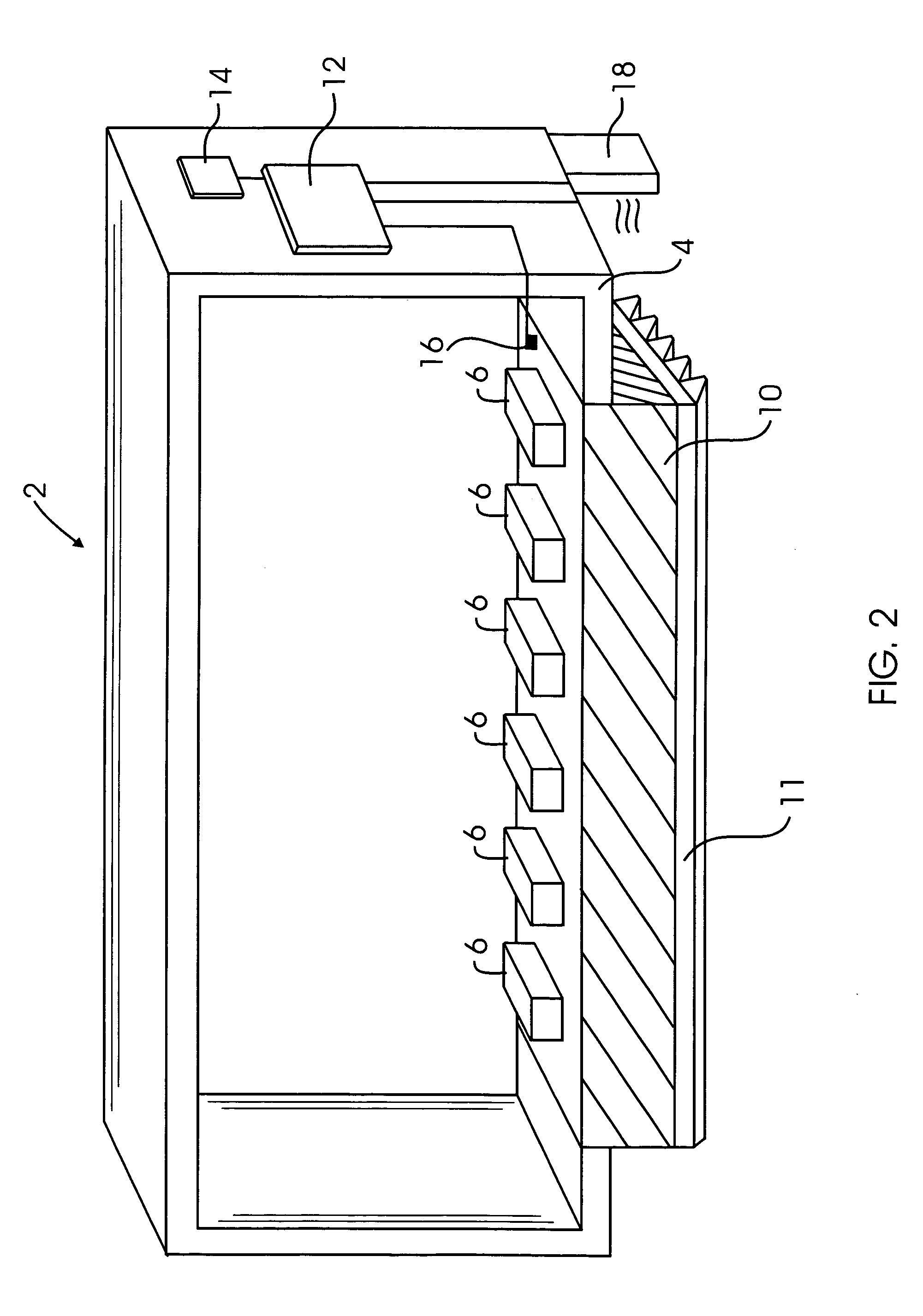
[0013]FIG. 1 illustrates a dielectric-based device 2 according to a preferred aspect of the invention. The device 2 includes a housing 4 or other compartment containing one or more filters 6. As best shown in FIG. 2, the filters 6 are filters which include a metal housing having a plurality of holes or cavities therein. Dielectric “pucks” are then placed inside the holes in the metal housing to form the complete three-dimensional filter 6. Such filters are known to those skilled in the art. The housing 4 is preferably formed from a thermally insulative material such as, for example, foam. It should be appreciated, however, that other thermal insulators may also be used in accordance with the present invention. The housing 4 may even have one or more thermally insulative layers deposited on a thermally conductive material. For example, the housing 4 may comprise a metallic or thermally conductive interior which is surrounded on the exterior with a thermal insulator such as foam or th...


PUM


Abstract

A dielectric-based filter includes a thermally insulated housing, at least one filter formed from a dielectric material disposed inside the insulated housing, and a temperature maintenance device having a heating component and a cooling component for maintaining the temperature of the filter inside of the insulated housing within a temperature range. In a preferred aspect of the invention, the temperature maintenance device includes a thermoelectric cooler. The device permits the use of temperature-dependent low loss, high dielectric constant materials in filtering / resonator applications. During operation of the device, the dielectric-based filter is maintained at substantially room temperature.

Description

REFERENCE TO RELATED APPLICATIONS[0001]This Application claims priority to U.S. Provisional Patent Application No. 60 / 601,745 filed on Aug. 13, 2004. U.S. Provisional Patent Application No. 60 / 601,745 is incorporated by reference as if set forth fully herein.FIELD OF THE INVENTION[0002]The field of the invention generally relates to dielectric-based filters (or resonators) used, for example, in base station filters in wireless applications. More specifically, the field of the invention relates to temperature stabilizing methods and devices incorporating low loss, high dielectric constant materials.BACKGROUND OF THE INVENTION[0003]Wireless base stations operating using one or more dielectric filters comprised of resonator “pucks” are becoming more common because of increasing demands for filtering of signals both on the transmit and receive sides. Dielectric-based resonators are attractive for wireless applications because they have low loss (i.e., high Q values). Unfortunately, ther...

Claims


Application Information

Patent Timeline
Patent Type & Authority Patents(United States)
IPC IPC(8): H01P1/20
CPCH01P1/30
Inventor EDDY, MICHAEL
Owner ANTONE WIRELESS CORP
Learn More