
Analog to digital converter

a digital converter and analog technology, applied in the field of analog to digital converters, can solve the problems of difficult to achieve, flash converters are known to provide high conversion speed, source of conversion error, increased cost, etc., and achieve the effect of increasing capacitance, reducing thermal noise on capacitors, and increasing thermal nois

Active Publication Date: 2007-07-31
ANALOG DEVICES INC
View PDF15 Cites 29 Cited by
  • Summary
  • Abstract
  • Description
  • Claims
  • Application Information

AI Technical Summary

Benefits of technology

This approach improves signal-to-noise power ratio and allows for effective error correction without additional bit trials, enabling higher performance and accuracy in analog to digital conversion without increasing power consumption or cost.

Problems solved by technology

These objectives are generally opposed, and become more difficult to achieve when a user also seeks for such devices to be relatively inexpensive.
Flash converters are known to provide high conversion speed, albeit at increased cost and with limited resolution.
The formation of sums and differences in the analog domain could give rise to a source of conversion error.
One of these shortcomings results from the fact that, in the real world, components and systems, are noisy, whether this noise comes via the power supply lines, or is from self generated thermal noise.
The first option, that is tripling the die area and the power consumption is generally not favoured as it makes the device more expensive to manufacture and less likely to be adopted by users as it eats into their power budget, which is particularly important in the context of mobile devices which are battery powered.
However simply making the individual converters smaller carries a noise penalty.
It could therefore be seen that smaller capacitors have greater thermal noise appearing at their terminals.
In the arrangement of U.S. Pat. No. 6,239,734 thermal noise occurring at any one of the successive approximation converters can result in that converter giving a false result and will skew the entire conversion process.
This probably does not represent an issue with the context of the 6 bit of the converter, but with modern converters requiring 12 bit or greater accuracy, the presence of noise in the real world is now a significant factor in analog to digital converter design.

Method used


Image

  • Analog to digital converter
  • Analog to digital converter
  • Analog to digital converter

Examples


Embodiment Construction

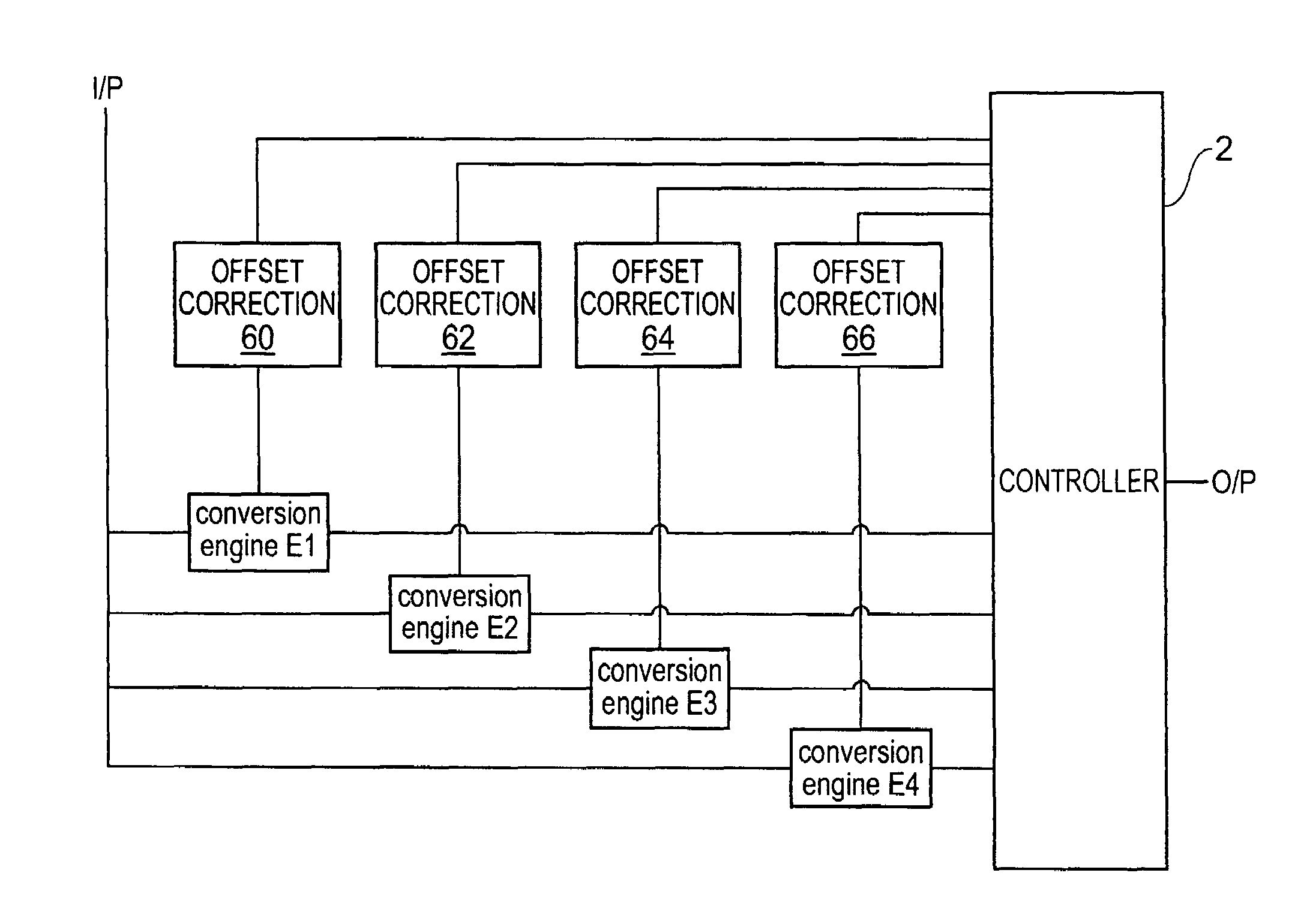
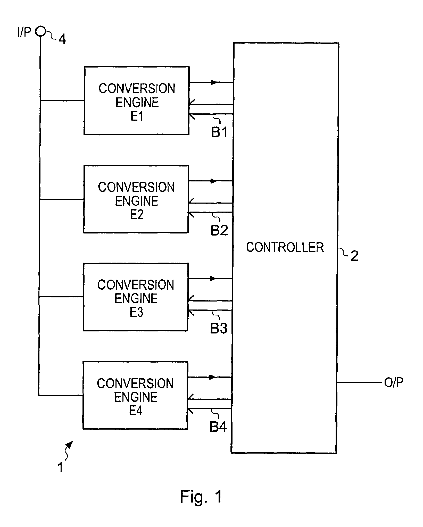
[0046]FIG. 1 schematically illustrates a successive approximation analog to digital converter, generally labelled 1, constituting an embodiment of the present invention. The converter comprises a plurality of analog to digital conversion engines which, advantageously, are switched capacitor analog to digital converters having the occasional redundant capacitor. These redundant capacitors are additional to the normal binary weighted bits and provide some correction of errors made in previous bit trials. Three conversion engines labelled E1, E2 and E3 are provided, although in a preferred embodiment of the present invention a fourth engine labelled E4 is also provided. Each of the engines E1 to E4 is in communication with a controller generally designated 2 which receives an output from a comparator provided internally within each of the conversion engines E1 to E4, and which also has a control bus designated B1 to B4 for controlling the switches associated with each of the capacitors...


PUM


Abstract

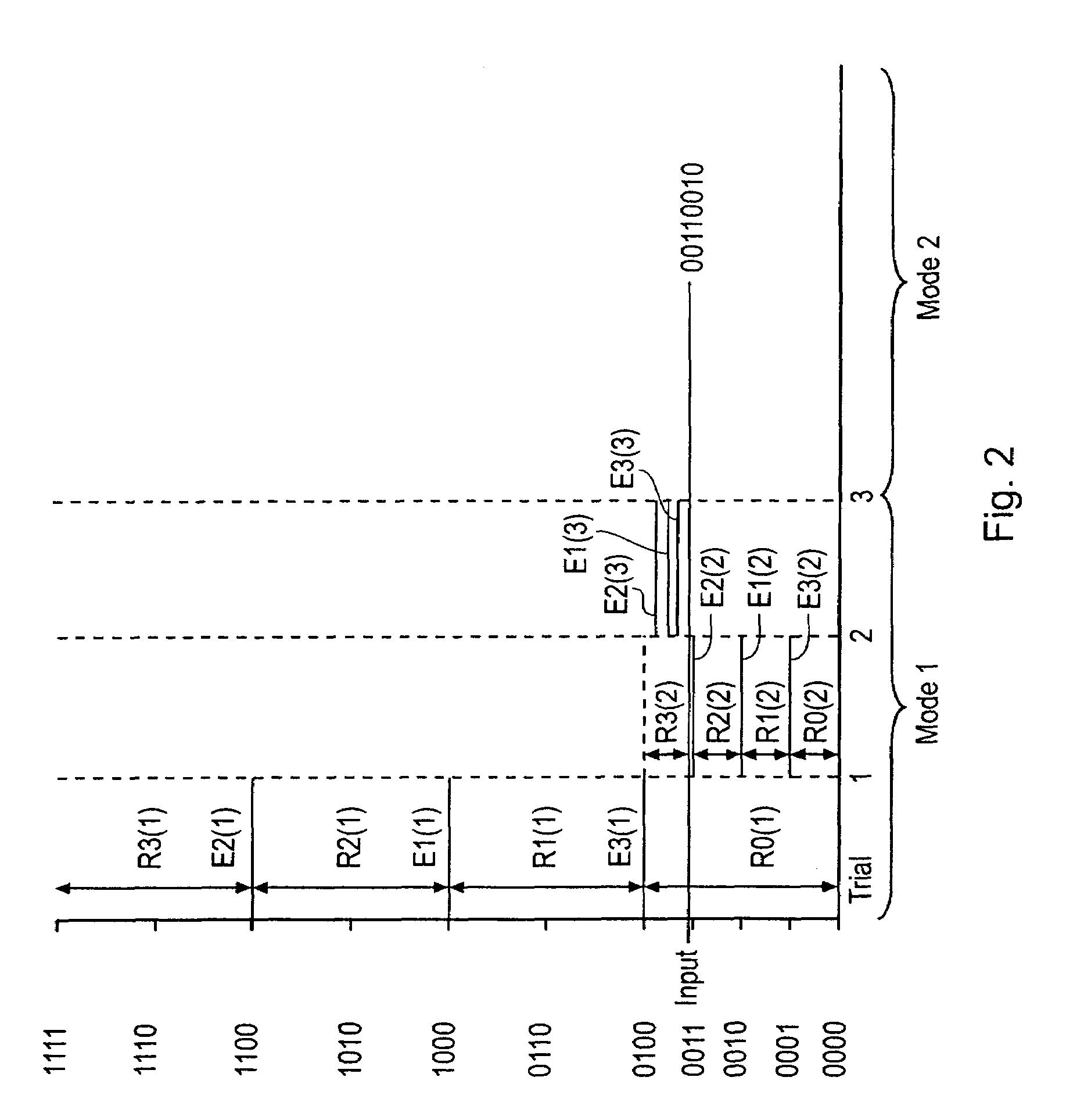
An analog to digital converter comprising at least two analog to digital conversion engines and a controller for controlling the operation of the analog to digital conversion engines such that during a first phase of an analog to digital conversion process the engines collaborate such that a plurality of bits can be determined during a single trial step; and during a second phase of the analog to digital conversion the conversion engines work independently; and the controller receives the outputs of at least one of the conversion engines and processes them to provide an output word.

Description

FIELD OF INVENTION[0001]The present invention relates to an analog to digital converter using a plurality of conversion engines acting in a co-operative state for a first part of a conversion cycle to allow multiple bits to be examined at each trial.BACKGROUND OF THE INVENTION[0002]Users of analog to digital converters generally wish to see high conversion accuracy and high conversion rates. These objectives are generally opposed, and become more difficult to achieve when a user also seeks for such devices to be relatively inexpensive.[0003]Flash converters are known to provide high conversion speed, albeit at increased cost and with limited resolution. In essence a flash converter consists of a plurality of comparators, each comparator connected to a respective tap on a resistor chain such that each converter is responsible for testing for one, and only one, of the possible digital outputs. Therefore an 8 bit flash converter requires 255 individual comparators to be fabricated ther...

Claims


Application Information

Patent Timeline
Patent Type & Authority Patents(United States)
IPC IPC(8): H03M1/48
CPCH03M1/144H03M1/0643H03M1/0678H03M1/0695H03M1/1019H03M1/46
Inventor HURRELL, CHRISTOPHER PETERPRICE, COLIN CHARLES
Owner ANALOG DEVICES INC
Learn More