Method and apparatus for measuring biological condition

a biological condition and measurement method technology, applied in the field of living body biological condition measurement methods and apparatuses, can solve the problems of disturbing the blood flow in the peripheral arteries, and affecting the accuracy of biological condition measurement, so as to reduce the adverse effect of measuring accuracy of biological condition and accurately detecting biological condition

Active Publication Date: 2007-08-07
DENSO CORP
View PDF20 Cites 111 Cited by
  • Summary
  • Abstract
  • Description
  • Claims
  • Application Information

AI Technical Summary

Benefits of technology

[0023]Accordingly, it is an object of the present invention to provide a method and an apparatus for measuring a biological condition of a living body, which are capable of reducing adverse effects on the measuring accuracy of the biological condition, thereby accurately detecting the biological condition of the living body, such as a pulsebeat thereof.

Problems solved by technology

This method, however, when measuring the heartbeat, it is necessary to affix at least one electrode pad on a portion of the living body, and it is tedious to carry out the affixing works of the at least one electrode pad.
The movement of the measurement portion of the living body on which the optical pulse sensor is fitted in daily life or in exercise causes the blood flowing in the peripheral arteries to be disturbed.
This interferes with the use of the pulse rate in substitution of the heartbeat rate.
This characteristic makes ineffective to use frequency-filtering operation of the pulse wave that is applied for usual noise rejection operations.
The technique disclosed in the former Patent Publication, however, even if the exercise noise sensor can detect the exercise noises, cannot detect noises generated related to the living body itself, such as noises generated due to the light components reflected from the surface of the measurement portion, such as the skin surface thereof.
Because of the change of relationship, it is difficult for the disclosed unique signal processing in the technique to accurately obtain the pulse wave components in the bloods.

Method used


Image

  • Method and apparatus for measuring biological condition
  • Method and apparatus for measuring biological condition
  • Method and apparatus for measuring biological condition

Examples


first embodiment

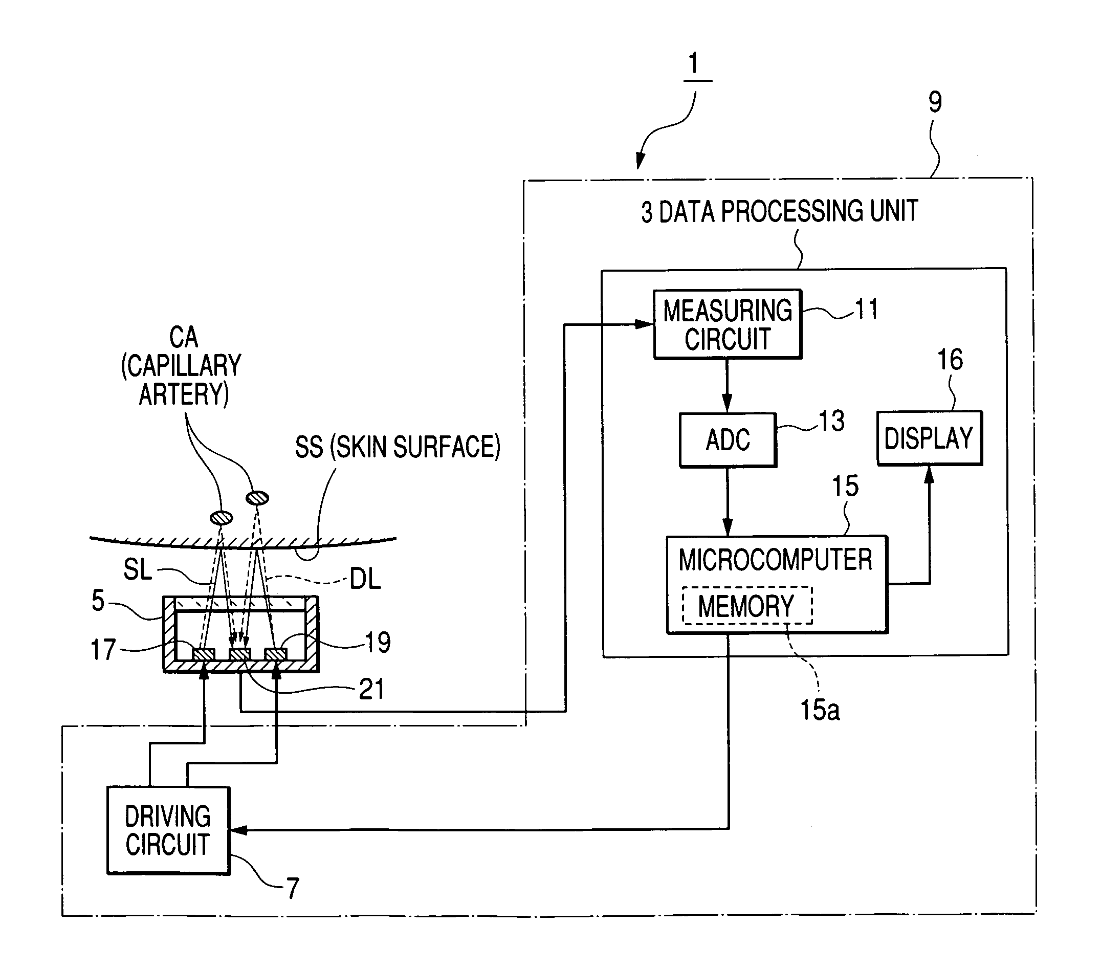
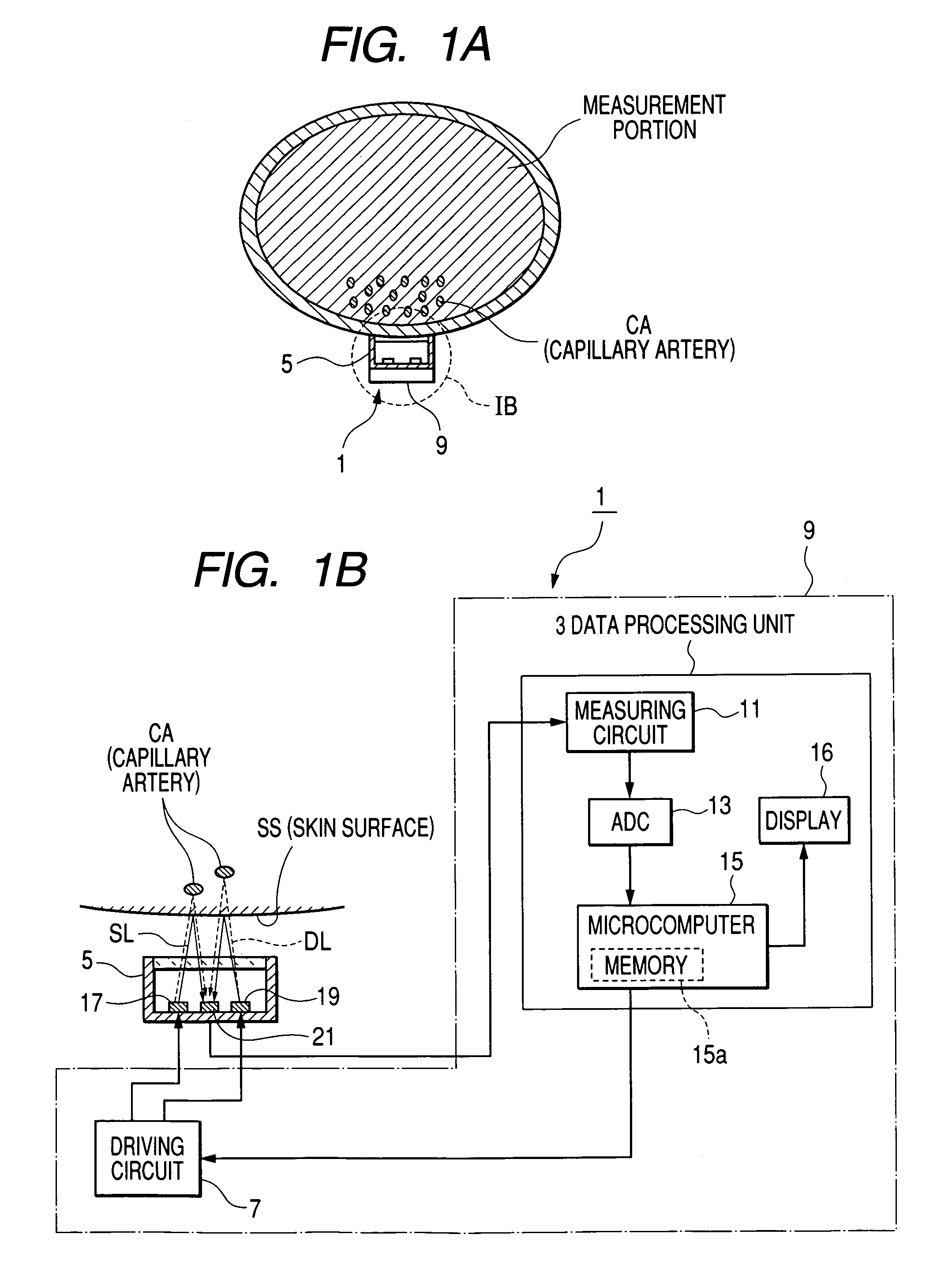
[0051]FIG. 1A is a view illustrating such a state that a biological condition measuring apparatus for executing a pulse wave measuring method as a biological condition measuring method according to a first embodiment of the invention is fitted to a measurement portion MP of a living body, such as a human body. FIG. 1B is a block diagram of the measuring apparatus illustrated in FIG. 1A, which is capable of detecting, as a biological condition, a pulse wave of the human body.

[0052]The measuring apparatus 1, as shown in FIG. 1, is composed of a data processing unit 3, a pulse wave sensor 5 communicable with the data processing unit 3, and a driving circuit 7 communicable with the data processing unit 3.

[0053]The data processing unit 3 includes a measuring circuit 11 having a cut-off filter for allowing some components of a signal inputted from the pulse wave sensor 5 that are not less than a predetermined cut-off frequency and cutting off other components that are less than the predet...

second embodiment

[0129]A second embodiment of the present invention will be described hereinafter.

[0130]In the second embodiment, elements of a biological condition measuring apparatus according to the second embodiment that are the same as those of the biological condition measuring apparatus 1 according to the first embodiment are omitted or simplified.

[0131]In this second embodiment, the infrared LED 17 and the green LED 19 emit the infrared light and the green light that have substantially same intensity, respectively.

[0132]The reflected lights based on the infrared light and the green light are detected by the PD 21, and the detection signals by the PD 21 are inputted to the measuring circuit 11, so that the measuring circuit 11 cuts off the direct current components of the detection signals, respectively, which is similar to the measuring process of the first embodiment.

[0133]Then, in this second embodiment, the measuring circuit 11, in order to change the sensitivity of the detection signal b...

third embodiment

[0137]A third embodiment of the present invention will be described hereinafter.

[0138]In the third embodiment, elements of a biological condition measuring apparatus according to the third embodiment that are the same as those of the biological condition measuring apparatus 1 according to the first embodiment are omitted or simplified.

[0139]The infrared LED 17 and the green LED 19 emit the infrared light and the green light that have substantially same intensity, respectively.

[0140]The reflected lights based on the infrared light and the green light are detected by the PD 21. The detection signals by the PD 21 are inputted to the measuring circuit 11. The direct current components of the detection signals are cut off, respectively, and they are amplified by the measuring circuit 11 by the same gain, respectively.

[0141]The amplified detection signals are transmitted to the microcomputer 15, and are frequency-analyzed thereby so that the pulsebeat components and the movement component...


PUM


Abstract

In an apparatus for measuring a biological condition of a living body, a light emitting unit emits individually first and second lights to a measurement portion of the living body. The first and second lights have first and second wavelengths, respectively. The first and second wavelengths are different from each other. A light receiving unit receives first and second reflection lights to generate first and second detection signals based on the first and second reflection lights, respectively. The first and second reflection lights are based on the first light reflected from the measurement portion and the second light reflected therefrom, respectively. The first and second detection signals have different characteristics from each other due to the difference between the first and second wavelengths. A measuring unit measures the biological condition based on the different characteristics of the first and second detection signals.

Description

BACKGROUND OF THE INVENTION[0001]The present invention relates to a method and an apparatus for measuring a biological condition of a living body, such as the pulse rate thereof.[0002]Recently, needs of monitoring the heartbeat rate of a living body, such as a human body, increase during exercise, such as jogging for health maintenance.[0003]One of usual methods of measuring the heartbeat rate is to measure an action potential along with a heartbeat of a living body from the chest region to obtain an electrocardiogram, and to calculate an interval between the adjacent amplitude peaks of the electrocardiogram wave.[0004]This method, however, when measuring the heartbeat, it is necessary to affix at least one electrode pad on a portion of the living body, and it is tedious to carry out the affixing works of the at least one electrode pad.[0005]It is considerable to, therefore, as one of more simplified methods, measure pulse waves in the living body to detect a pulse rate of the livin...

Claims


Application Information

Patent Timeline
Patent Type & Authority Patents(United States)
IPC IPC(8): A61B5/02A61B5/0245A61B5/024A61B5/11
CPCA61B5/02416A61B5/11
Inventor KIMURA, TEIYUUKAWACHI, TAIJISAKAI, KAZUHIRO
Owner DENSO CORP
Why Eureka
Try Eureka