Power transmission shaft

a transmission shaft and power technology, applied in the direction of heat treatment equipment, manufacturing tools, furnaces, etc., can solve the problems of increasing costs, increasing costs, and the possibility of a decrease in the shear strength of the hollow shaft, so as to prevent the generation, stable torsion fatigue strength, and high reliability

Inactive Publication Date: 2007-08-07
NTN CORP
View PDF16 Cites 2 Cited by
  • Summary
  • Abstract
  • Description
  • Claims
  • Application Information

AI Technical Summary

Benefits of technology

[0014]According to the present invention, as described above, the inner diametrical surface is subjected to the hardening treatment, so that it becomes possible to ensure a hardness to be required for the power transmission shaft. In addition, such a resulting hardness allows to prevent the generation of wrinkle on the inner diametrical surface by a plastic working to be effected as an origin of breakage. As a result, the power transmission shaft that ensures a stable torsion fatigue strength and having a high reliability and a long useful life can be obtained.
[0015]Furthermore, by applying a predetermined residual compression stress on the outer diametrical surface of the power transmission shaft, the residual compression stress increases. As a result, it becomes possible to further increase the torsion fatigue strength. Such a residual compression stress can be easily applied by a shot peening treatment. In addition, the residual compression stress may be preferably 750 MPa or more.

Problems solved by technology

However, it will effect an increase in costs because of increasing the weight and the cutting amount of a coupling portion.
However, it will lead to an increase in costs because of increasing the number of structural components and the number of assembling steps in the manufacturing process.
Therefore, there is a possibility of a decrease in the shear strength of the hollow shaft.
Therefore, the welded portion of an electro-unite part of the welded pipe, which extends in the axial direction, tends to be broken, leading to a decrease in the strength of the power transmission shaft.
Thus, there is a tendency in which the inner radial surface of the hollow shaft become wrinkled.
Such a wrinkle may become the origin of breakage, causing a decrease in the strength of the power transmission shaft.

Method used


Image

  • Power transmission shaft
  • Power transmission shaft
  • Power transmission shaft

Examples


Embodiment Construction

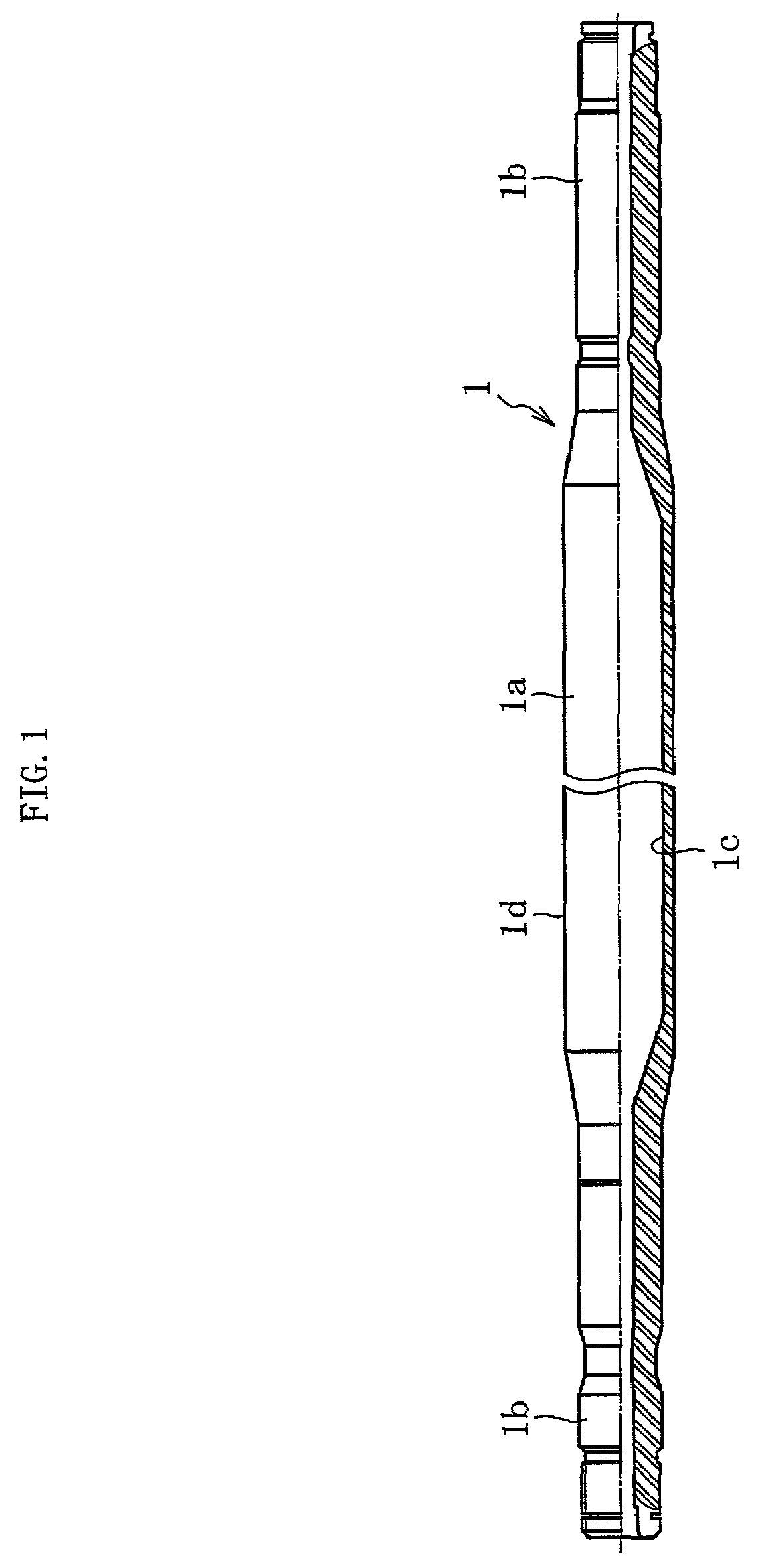
[0023]FIG. 1 shows a power transmission shaft as one of preferred embodiments of the present invention. The power transmission shaft 1 is provided as an integral-type hollow shaft. That is, the power transmission shaft 1 comprises: a middle pipe part 1a having a largest diameter portion, compared with the others; and axial parts 1b provided on the opposite ends of the middle pipe part 1a in which a coupling portion such as a spline is formed on the outer periphery of each end portion of the axial parts 1b. These parts 1a, 1b are integrally shaped from the same element tube.

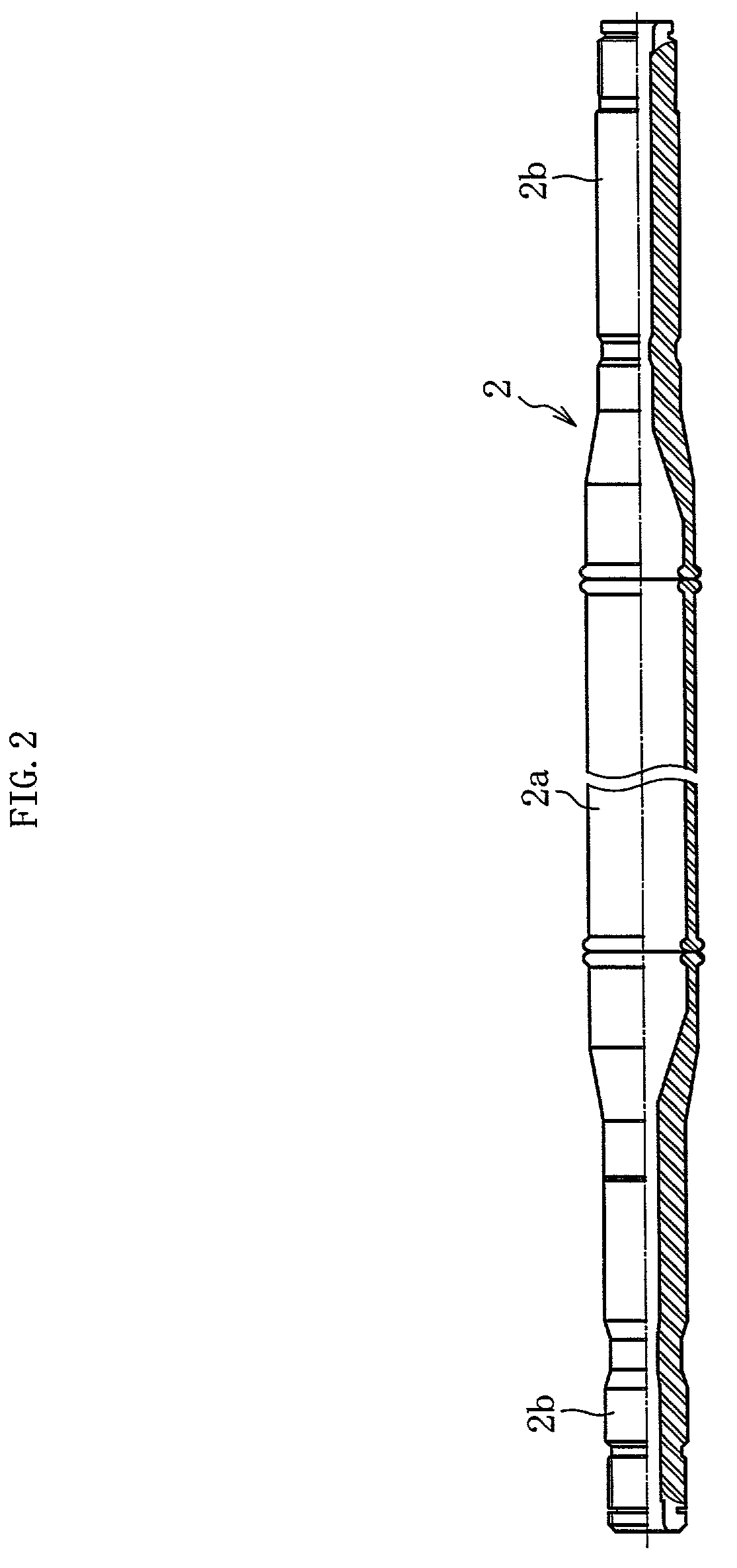
[0024]Referring now to FIG. 2, there is shown a power transmission shaft as an alternative preferred embodiment of the present invention. In this embodiment, the power transmission shaft 2 may be provided as a joined-type hollow shaft. That is, this shaft is fabricated by joining a pipe part 2a and axial parts 2b by welding such as friction pressure welding, or the like. In this case, it is noted that these parts ...


PUM

PropertyMeasurementUnit
Rockwell hardness HRCaaaaaaaaaa
Rockwell hardnessaaaaaaaaaa
Rockwell hardness HRCaaaaaaaaaa

Abstract

A power transmission shaft having an improved strength and ensuring a stable torsion fatigue strength. The power transmission shaft has coupling members respectively provided on the opposite ends of an pipe part made of a steel material. The steel material includes 0.30-0.45% by weight of C, 0.05-0.35% by weight of Si, 1.0-2.0% by weight of Mn, 0.05% by weight or less of Al, 0.01% by weight or less of S, and the remainder (iron Fe and unavoidable impurities). The pipe part has an electro-unite portion that extends in the axial direction. The electro-unite portion and neighborhood thereof are hardened so as to have a Rockwell hardness HRC of 45 or more. Also, another power transmission shaft has coupling members integrally formed on opposite ends thereof. In addition, the shaft is formed from a steel element tube by a plastic working. The shaft has an inner diametrical surface which is subjected to a high-frequency induction hardening and tempering treatment to make the surface portion hardness of the inner diametrical surface to have a Rockwell hardness HRC of 35 or more.

Description

BACKGROUND OF THE INVENTION[0001]1. Field of the Invention[0002]The present invention relates to a power transmission shaft to be used as, for example, a drive shaft or a propeller shaft, which constitutes a part of a power transmission system in an automobile.[0003]2. Description of the Related Art[0004]In general, there are several kinds of transmission shafts that constitute a power transmission system of an automobile. The shafts include a drive shaft for connecting between an engine and a wheel-bearing device, a propeller shaft for transmitting power from a transmission to reduction gears, and so on. Each of these shafts has a coupling member such as a spline on the shaft-end. The power transmission shafts may be broadly classified in the group of solid shafts made of solid bars and the other group of hollow shafts made of steel pipes or the like, according to their basic structures.[0005]Conventionally, solid shafts have been used as power transmission shafts for automobiles. ...

Claims


Application Information

Patent Timeline
Patent Type & Authority Patents(United States)
IPC IPC(8): C22C38/04C21D9/28F16C3/02
CPCB21K1/063B21K1/12F16C3/02C21D9/28Y10T428/12965Y10S148/909F16C2326/06F16C2204/62
Inventor WAKITA, KAZUYAIKEI, KATSUYUKIKURA, HISAAKI
Owner NTN CORP
Why Eureka
Try Eureka