Amplifier system with current-mode servo feedback

a servo feedback and amplifier technology, applied in the direction of negative-feedback-circuit arrangement, amplifier combinations, instruments, etc., can solve the problems of unwanted signal components in externally applied input signals, and achieve the effect of accurately amplifying any subsequent variations of input signals and high output impedan

Inactive Publication Date: 2007-08-07
BIOURJA ENERGY SYSTEMS LLC
View PDF97 Cites 62 Cited by
  • Summary
  • Abstract
  • Description
  • Claims
  • Application Information

AI Technical Summary

Benefits of technology

[0028]A servo feedback loop is controlled by a high-gain differential amplifier configured as an integrator exhibiting a closed-loop gain that decreases with frequency at a rate of about 6 dB per octave. The integrator is provided at one input with a suitable reference potential that is usually ground, while the other input of the integrator is adapted to sample the main output signal. The integrator output is coupled to at least one controllable current source, yielding a current-mode feedback signal that is conveyed to a suitable node in the forward gain path of the amplifier apparatus. The unwanted DC components, or a limited range of low frequency signal components, are thereby substantially removed from the main output signal, leaving a residual signal that exhibits an average value substantially equal to a reference potential that is usually equal to ground. To maximize the dynamic range available in the forward signal path of the amplifier apparatus, no significant amount of signal amplification is applied ahead of the point where the servo feedback is injected into the circuit.
[0033]In another illustrative embodiment, means are provided whereby a servo correction value may first operate in a ‘track mode’ to establish an equilibrium condition, and a ‘hold mode’ to make the servo correction signal remain at a fixed value. The amplifier system can thereby accurately amplify any subsequent variations in the input signal. Such variations may represent not only continuously time-varying AC signals but also step-wise variations representing changes in the DC signal level.

Problems solved by technology

Such unwanted signal components may exist in externally applied input signals or may arise within the amplification circuitry itself.

Method used


Image

  • Amplifier system with current-mode servo feedback
  • Amplifier system with current-mode servo feedback
  • Amplifier system with current-mode servo feedback

Examples


Embodiment Construction

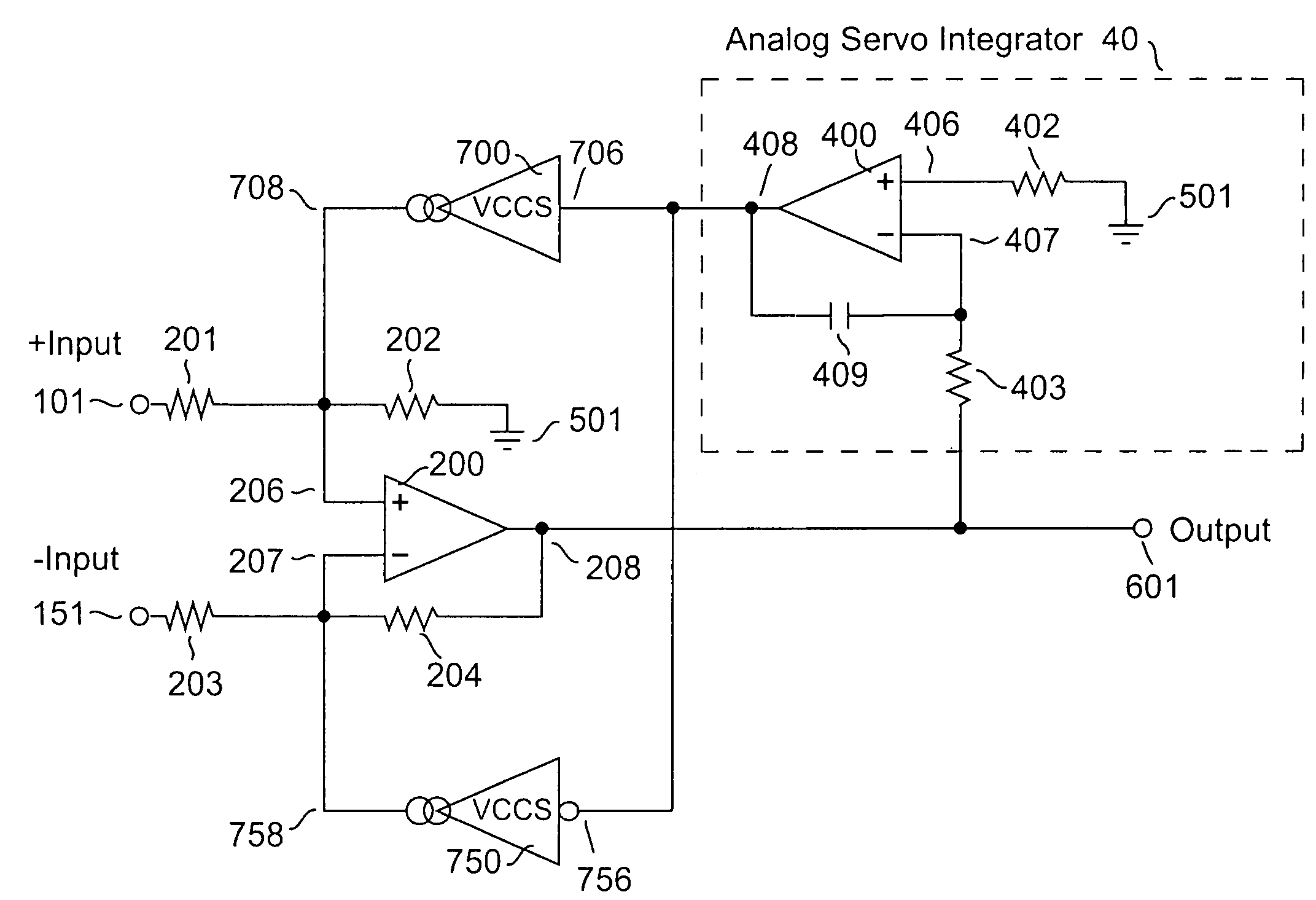
[0052]An illustrative embodiment of an amplifier apparatus according to the invention is depicted in FIG. 5. Differential amplifier 200, disposed in the forward gain path of an amplifier apparatus, constitutes a primary amplifier that receives a first input signal through impedance element 201 at its non-inverting input 206, and receives a second input signal through impedance element 203 at its inverting input 207, to produce main output signal 601. In practice, the potential on a first terminal of an external device-under-test (henceforth, DUT) represents the first input signal, while the potential on its second terminal represents the second input signal.

[0053]Within this embodiment and for each of the embodiments to be described subsequently, impedance elements 201 and 203 are typically resistors; impedance elements 202 and 204 are generally resistors, but additional capacitors may be added in parallel with each of these to provide local frequency compensation. The forward gain ...


PUM


Abstract

A system and method for compensating an amplifier apparatus for low frequency and / or DC components of an externally applied input signal as well as for any voltage offsets contributed by the amplifier circuitry. Band-limited servo feedback is applied to predetermined nodes in the forward gain path to null out unwanted signal components, leaving a residual signal that, when amplified, will be centered around ground, so that the full dynamic range of the amplifier system may be utilized. Consequently, the signal-to-noise ratio available at the output of the amplifier system will be maximized. The servo compensation may either operate in continuous time, or it may be held constant once a suitable level of compensation has been established, or it may be adjusted from time to time to accommodate slow variations of the average DC component of the input signal.

Description

CROSS REFERENCE TO RELATED APPLICATIONS[0001]This is a continuation in part of U.S. patent application Ser. No. 10 / 831,885 filed on Apr. 26, 2004 now U.S. Pat. No. 7,078,965 and U.S. patent application Ser. No. 10 / 443,230 filed on May 21, 2003 which are hereby incorporated by reference in their entirety.FIELD OF THE INVENTION[0002]The present invention relates to servo offset compensation for an amplifier, and more particularly, to controllable active feedback circuits which can substantially attenuate a DC signal component or a predetermined range of low frequency components present in the output signal of the amplifier.BACKGROUND OF THE INVENTION[0003]When it is desirable to use an amplifier to detect and amplify only the time-varying components of a signal that may also contain a non-zero static or average DC component, it is necessary to remove or otherwise null out this unwanted DC signal component. This may be achieved by inserting suitable high-pass networks in the forward si...

Claims


Application Information

Patent Timeline
Patent Type & Authority Patents(United States)
IPC IPC(8): H03F3/45G01R31/36
CPCG01R31/3004G01R31/31706G01R31/31716G01R31/3631H03F1/34H03F3/211H03F3/45475H03F3/45479H03F3/45968H03F2200/261H03F2200/91H03F2203/45138H03F2203/45212H03F2203/45521H03F2203/45592G01R31/386
Inventor LALETIN, WILLIAM H.
Owner BIOURJA ENERGY SYSTEMS LLC
Why Eureka
Try Eureka