
Low friction coatings for dynamically engaging load bearing surfaces

a load bearing surface and low friction technology, applied in the direction of valve member-seat contact, mechanical equipment, transportation and packaging, etc., can solve the problems of significant valve torque increase, loss of some of the mass and lubricating properties of expensive greases, and stable pri

Active Publication Date: 2007-08-14
VETCO GRAY LLC
View PDF10 Cites 40 Cited by
  • Summary
  • Abstract
  • Description
  • Claims
  • Application Information

AI Technical Summary

Benefits of technology

"The invention is about an apparatus for a well that has two components that slide against each other in a load-bearing manner. The sliding surfaces are coated with a polymer coating that contains stiffening particles, such as nanotubes. The coating is applied using a spray dispersion at room temperature. The technical effect of this invention is to provide a more durable and load-bearing surface for the well components, which can withstand higher temperatures and pressures."

Problems solved by technology

Additionally, only very expensive greases are stable to temperatures above 400 F and may lose some of their mass and lubricating properties.
The loss of lubrication at high temperatures leads to significant increases in valve torques and may lead to the galling of the mating surfaces.
Some polymer type coatings have been used on gate valves as well, but suffer from insufficient load bearing capacity and ductility especially at elevated temperatures.
A thermoplastic polymer coating tends to creep and flow under high contact stress and elevated temperatures.
A thermoset type of polymer coating does not soften with temperature as does a thermoplastic, but suffers from poor ductility and a propensity toward greater adhesion especially at elevated temperatures.
These properties generally result in cracks in the coating and the removal of the coating to its mated surface.

Method used


Image

  • Low friction coatings for dynamically engaging load bearing surfaces
  • Low friction coatings for dynamically engaging load bearing surfaces
  • Low friction coatings for dynamically engaging load bearing surfaces

Examples


Embodiment Construction

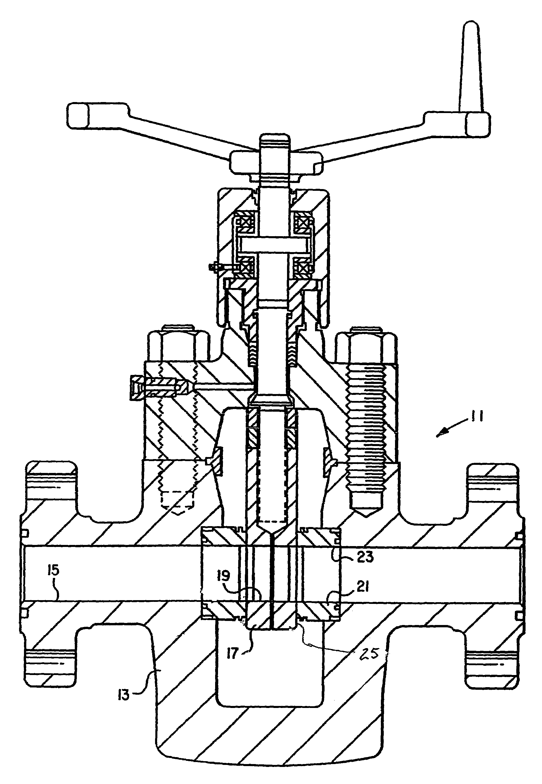
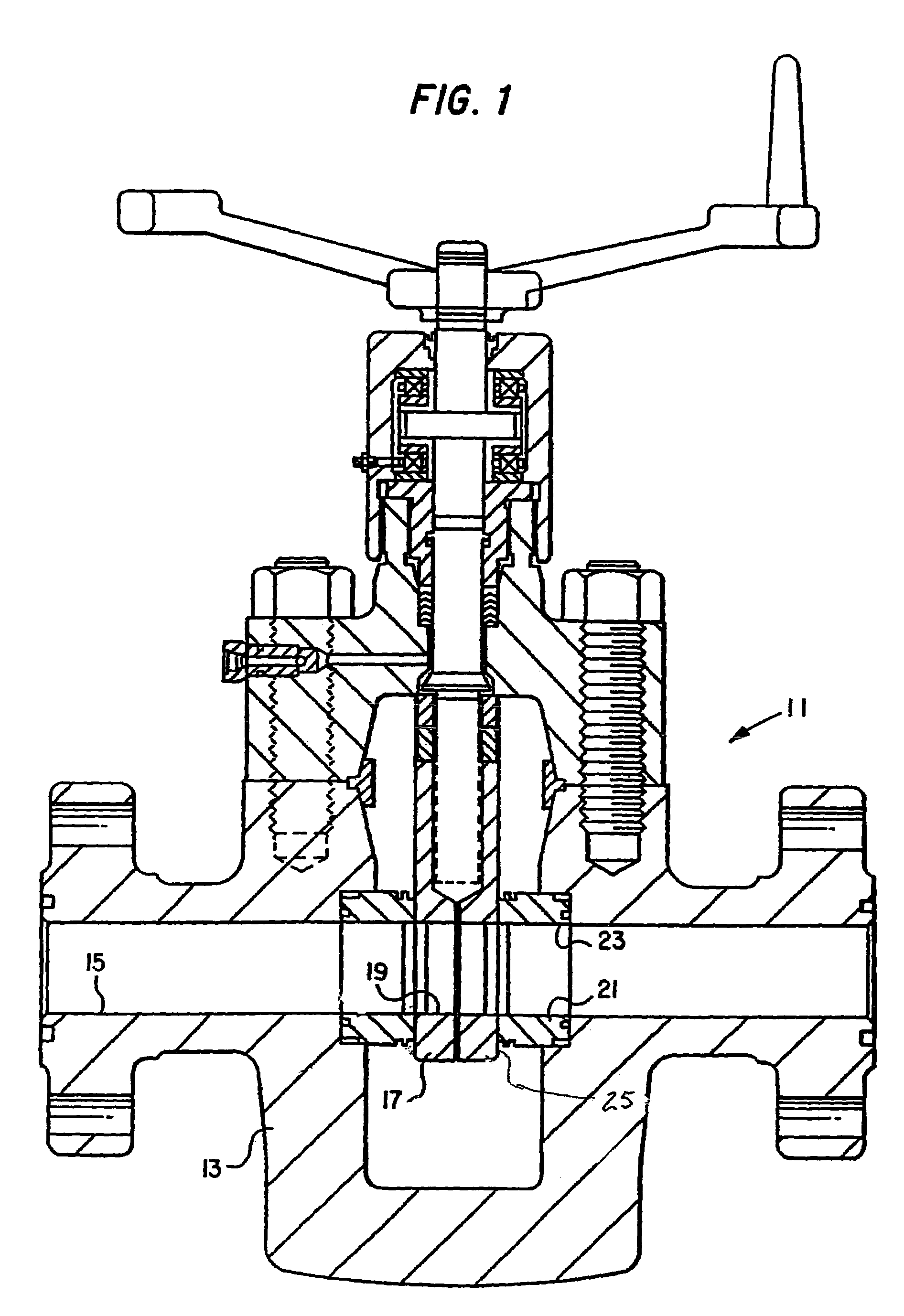
[0013]Referring to FIG. 1, gate valve 11 has a body 13 and a flow passage 15 that extends transversely through body 13. Valve 11 has a gate 17 with a hole 19 therethrough. Gate 17 is shown in the open position. The gate valve 11 shown in FIG. 1 is a non-rising-stem type valve, but the valve 11 may alternatively be a rising-stem type valve. Also shown in FIG. 1 are ring-shaped valve seats 21, which have holes 23 that register with the flow passage 15 of the valve. Gate valve 11 is shown as a split gate type having two separate slabs, but it could alternatively be a single slab type.

[0014]When gate 17 is in the open position, the hole 19 of the gate 17 registers with flow passage 15 of the valve 11, thereby allowing flow through the valve. When the gate is closed, the hole 19 no longer registers with the flow passage 15. The gate 17 has an engaging face 25 on each side that interfaces with seats 21. While gate 17 is closed, typically pressure in the flow passages 15 creates a substant...


PUM


Abstract

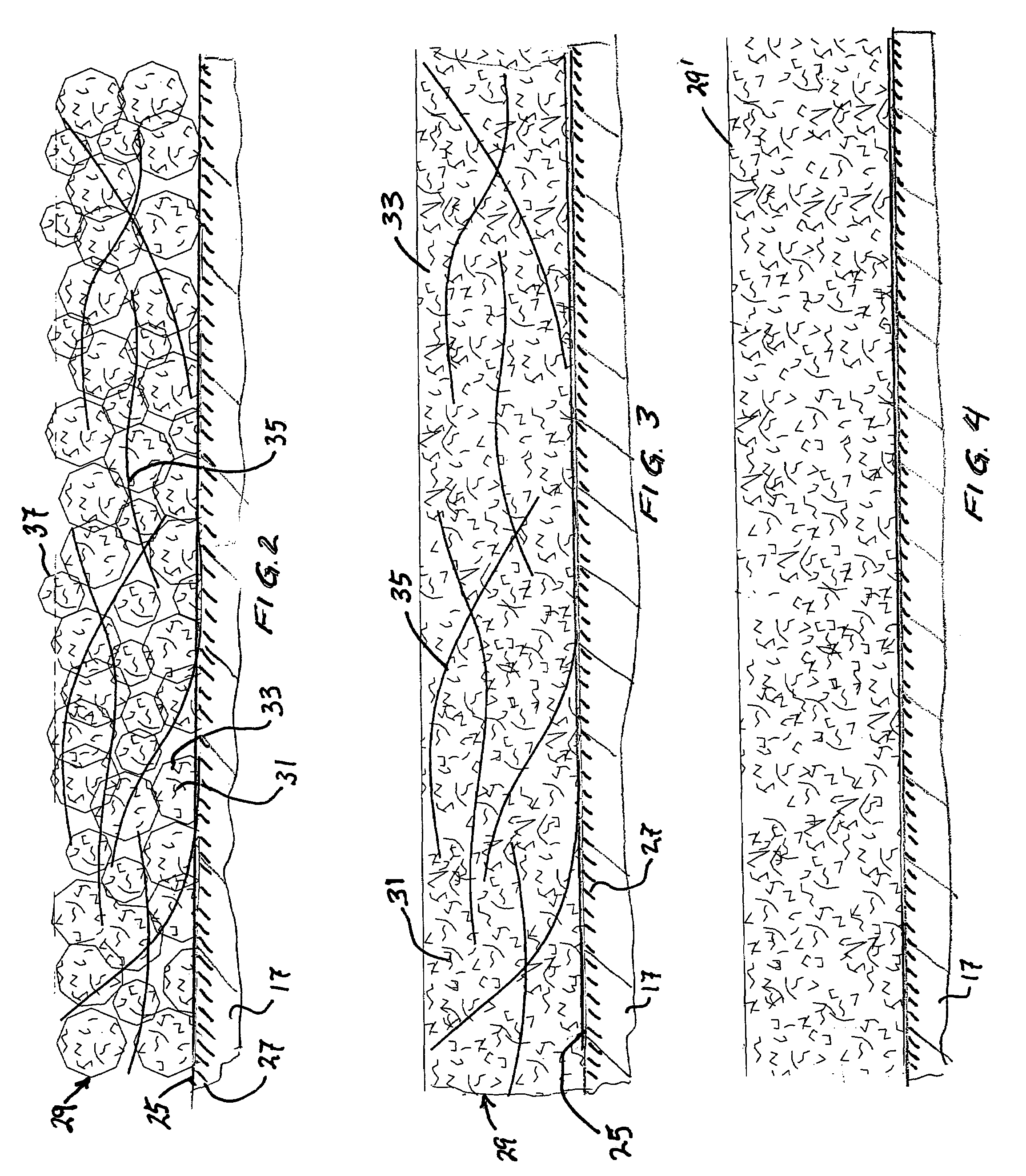
A gate valve has a body, the body having a cavity and a flow passage intersecting the cavity. A seat ring is mounted to the body at the intersection of the flow passage and the cavity, the seat ring having an engaging face. A gate in the cavity has an engaging face that slidingly engages the face of the seat ring while being moved between open and closed positions. A polymer coating is on at least one of the faces. The polymer contains a quantity of carbon nanotubes for stiffening.

Description

CROSS-REFERENCE TO RELATED APPLICATION[0001]This application claims priority to provisional application 60 / 605,176, filed Aug. 27, 2004.FIELD OF THE INVENTION[0002]The invention relates generally to low friction coatings formed on load bearing surfaces that slidingly engage each other, such as a gate and seat ring of a gate valve for a wellhead assembly.BACKGROUND OF THE INVENTION[0003]Gate valves are used when a straight-line flow of fluid and minimum flow restriction are required. When the valve is wide open, the gate is drawn into the opposite end of the valve cavity. The gate has an opening for flow through the valve the same size as the pipe in which the valve is installed. The valve provides an unobstructed passageway when fully open. It is best suited for main fluid supply lines and for pump lines, and is often used for oil and gas production where pressures may range from 5000 to 30,000 psi.[0004]Previous versions of gate valves have featured a coating on the exterior surfac...

Claims


Application Information

Patent Timeline
Patent Type & Authority Patents(United States)
IPC IPC(8): F16K3/00
CPCF16K3/02F16K3/0263F16K25/005Y10S977/963Y10T137/7036F16K3/36F16K25/04
Inventor HUNTER, RICK C.
Owner VETCO GRAY LLC
Learn More