Bone growth promoting implant

a growth-promoting, bone-building technology, applied in the field of bone-building-promoting implants and implants, can solve the problems of poor anchoring of metal implants, thin implants providing less stable support structures for the bone, and fretting wear of the bone, so as to achieve high flexibility and control, the effect of increasing strength and controlling the flexibility of the implan

Inactive Publication Date: 2007-08-14
ACTIVE IMPLANTS LLC +1
View PDF225 Cites 72 Cited by
  • Summary
  • Abstract
  • Description
  • Claims
  • Application Information

AI Technical Summary

Benefits of technology

[0013]According to the present invention, a high degree of flexibility and control is imparted to a nail-like implant by using a “spar” construction with adjustable tension cables and longitudinal structural members. The tension cables provide curvature control and support, and rigidity against bending and buckling of the nail-like implant. The longitudinal structural members and the tension cables become an integral part of a composite regenerated bone, which has a substantially increased strength over bone regenerated through the use of conventional implants, regardless of whether the nail-like implant remains inside the bone or whether a majority of the implant (except for the longitudinal structural members) is later removed. The flexibility of the implant is controlled by specifically varying the structural geometry and stiffness of certain portions of the implant, and by adjusting the tension in selected tension cables during and / or after the implantation operation to thereby adjust the stiffness of the implant. When the longitudinal structural members are inserted into the bone they have at most a low and generally uniform tension level, and preferably the structural members are free of tension during insertion. After insertion, the tension cables may be adjusted to provide additional stiffness to the longitudinal structural members and to produce a desired curvature therein by imparting asymmetric or non-uniform levels of tension thereto.
[0014]The present invention creates a stronger regenerated bone by providing a new type of cross-section for a bone implant and by promoting the growth of a composite bone structure.

Problems solved by technology

However, thin implants provide a less stable support structure for the bone.
Several problems are associated with conventional bone implants due to a mismatch between materials properties of the bone and the metal implant.
For example, contact between the metal implant and the bone may cause fretting wear of the bone.
Also, a difference in materials properties such as Young's modulus and thermal expansion coefficient between the metal implant and the bone may result in poor anchoring of the metal implant to the bone, which may cause discomfort to the patient, especially during weather changes.
Furthermore, conventional metal implants provide virtually no shock absorption or damping.
One problem with conventional metal implants is that they tend to distribute stress unevenly to the surrounding bone, with some surrounding bone areas receiving excessive stress levels and other surrounding bone areas receiving less than optimal stress levels.
In extreme cases where the amount of stress imparted to a surrounding bone area is too low, the conventional metal implant may contribute to atrophy or degeneration of the area because of lack of use.
This, in turn, may lead to bone recession and loosening of the anchoring of the metal implant, thus creating an undesirable gap between the bone and the metal implant.
Another problem with conventional metal implants is their tendency to interfere with diagnostic techniques such as magnetic resonance imaging (MRI) and related tomographic techniques.
Metal implants produce shadows, or image artifacts, because the metal material of the implants tends to interfere with the magnetic characteristics of the implant region, thus distorting the magnetic image of that region.
These shadows reduce the effectiveness of magnetic resonance techniques, which are important and widely used diagnostic techniques that have even been used during surgical operations to produce real-time images with simultaneous multiple image sections.
Yet another drawback of conventional implants is their inability to conform to the three-dimensionally curved surfaces of a bone canal, thus reducing their effectiveness in inducing or promoting continuous bone growth or bone reinforcement for strengthening the bone.

Method used


Image

  • Bone growth promoting implant
  • Bone growth promoting implant
  • Bone growth promoting implant

Examples


Embodiment Construction

[0029]Preferred embodiments of the present invention are described below with reference to the accompanying drawings, in which like reference numerals represent the same or similar elements.

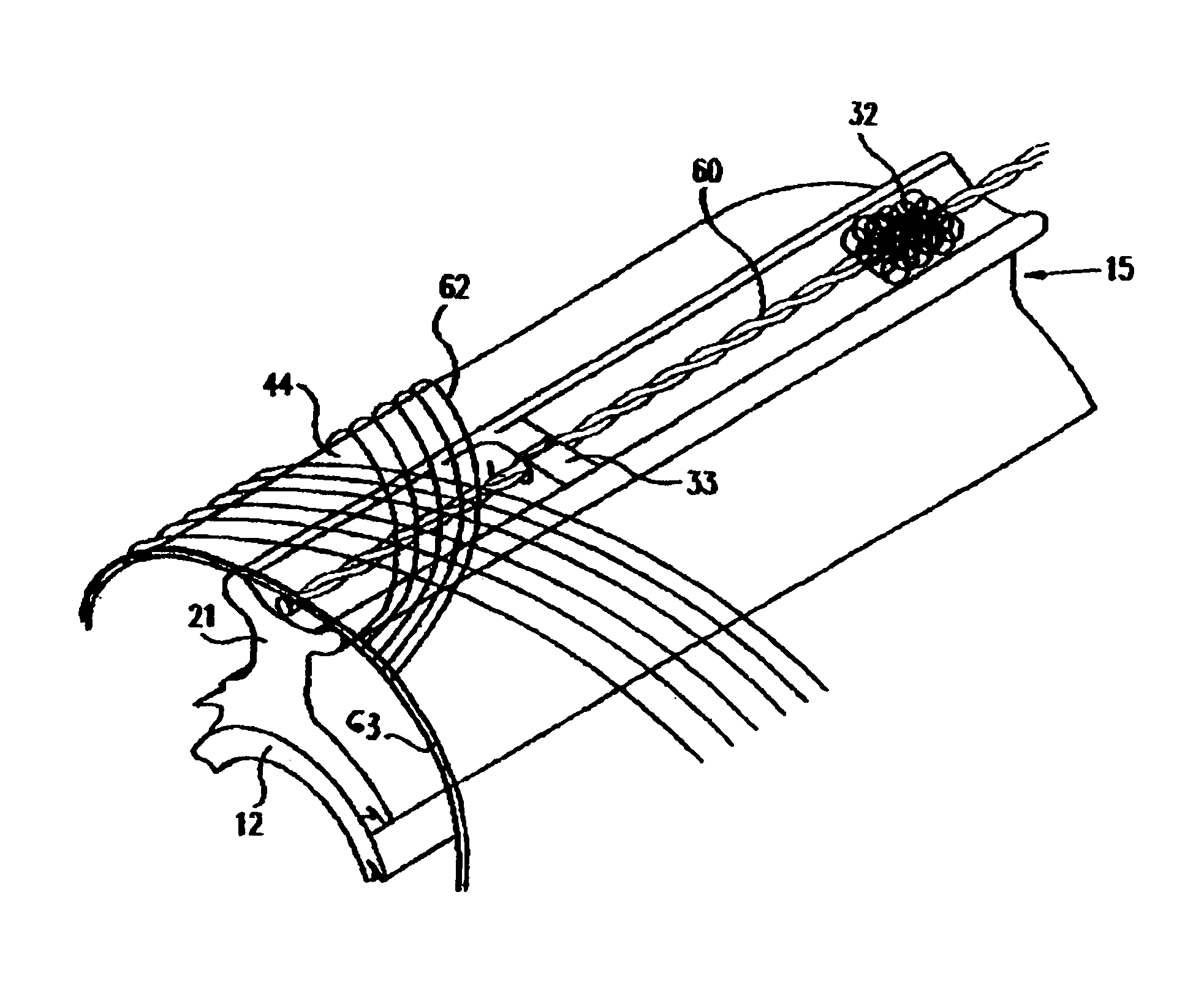
[0030]It is generally known that a body recognizes a minimum level of stress in its bones. New bone cells are generated when an amount of stress is exerted thereto that falls within a preferred range of values that are above a certain lower limit and below a certain upper limit. A conventional stem-type or nail-type implant is constructed to have an average geometric shape that does not conform to the three-dimensionally curved surfaces of a bone canal in which the implant is inserted. In addition, contact between the implant and the bone occurs at random regions and is generally not sufficiently continuous to promote optimal bone growth. Because of the randomness of the contact between the implant and the bone, the forces exerted by the implant on the bone produce random stress levels within the...


PUM

PropertyMeasurementUnit
stiffnessaaaaaaaaaa
tensionaaaaaaaaaa
forceaaaaaaaaaa

Abstract

A stem-like bone implant includes longitudinal structural members and tension cables that provide curvature control and support, and rigidity against bending and buckling. The longitudinal structural members and tension cables may become an integral part of a composite regenerated bone having a substantially increased strength over natural bone. The flexibility of the implant is controlled by specifically varying the structural geometry of certain portions of the implant, and by adjusting the tension in the tension cables before, during and after the implantation operation to thereby adjust the stiffness of the implant. The tension cables may be adjusted to produce asymmetric or non-uniform levels of tension in the longitudinal structural members.

Description

FIELD OF THE INVENTION[0001]The present invention relates generally to bone implants. More specifically, the present invention relates to bone-growth promoting implants and implants that promote the growth of composite bone material.BACKGROUND OF THE INVENTION[0002]Conventional bone prostheses or implants that are known in the art generally include a metal portion constructed of steel or titanium inserted in and fixedly attached to a bony portion of a patient's body. For example, conventional implants for stems of articulating joints or for nail-like implants used for intramedullary fixation to support bones during healing of fractures are constructed of metal. The nail-like implants are usually, but not always, removed when healing is complete.[0003]Current implant technology may be divided into two broad categories: implants which require reaming of an inner canal in the bone before insertion of the implant, generally typical of relatively thick implants; and implants which do not...

Claims


Application Information

Patent Timeline
Patent Type & Authority Patents(United States)
IPC IPC(8): A61F2/28A61B17/58A61B17/00A61B17/72A61B17/80A61B17/86A61F2/00A61F2/02A61F2/30A61F2/32A61F2/36A61F2/46A61F2/48
CPCA61B17/7208A61B17/8085A61B17/7258A61B17/7266A61B17/86A61B2017/00539A61F2/28A61F2/30724A61F2/30767A61F2/30965A61F2/3662A61F2002/2817A61F2002/2825A61F2002/286A61F2002/30009A61F2002/30014A61F2002/30018A61F2002/30062A61F2002/3008A61F2002/30158A61F2002/30179A61F2002/30207A61F2002/30217A61F2002/30235A61F2002/30462A61F2002/305A61F2002/30546A61F2002/30565A61F2002/30581A61F2002/30593A61F2002/30596A61F2002/30604A61F2002/30878A61F2002/30879A61F2002/30892A61F2002/30894A61F2002/30952A61F2002/4631A61F2002/48A61F2210/0004A61F2220/0025A61F2220/0075A61F2230/0026A61F2230/0058A61F2230/0067A61F2230/0069A61F2250/0012A61F2250/0018A61F2250/0028A61F2250/0029A61F2250/006A61F2250/0098A61F2310/00796A61F2310/00928A61F2310/00958A61F2310/00976A61F2002/30594A61F2/48
Inventor STEINBERG, AMIRAM
Owner ACTIVE IMPLANTS LLC
Why Eureka
Try Eureka