Apparatus for monitoring optical signal-to-noise ratio

a technology of optical signal and antenna, which is applied in the direction of transmission monitoring, multimode transmission, fibre transmission, etc., can solve the problems of reducing the performance of optical signals, reducing the optical signal-to-noise ratio, and high cost, so as to effectively operate, maintain and manage a wdm optical network

a technology of optical signal and antenna, which is applied in the direction of transmission monitoring, multimode transmission, fibre transmission, etc., can solve the problems of reducing the performance of optical signals, reducing the optical signal-to-noise ratio, and high cost, so as to effectively operate, maintain and manage a wdm optical network

US7257324B2Inactive Publication Date: 2007-08-14KOREA ADVANCED INST OF SCI & TECH

Image

  • Apparatus for monitoring optical signal-to-noise ratio
  • Apparatus for monitoring optical signal-to-noise ratio
  • Apparatus for monitoring optical signal-to-noise ratio

Examples


embodiment 1

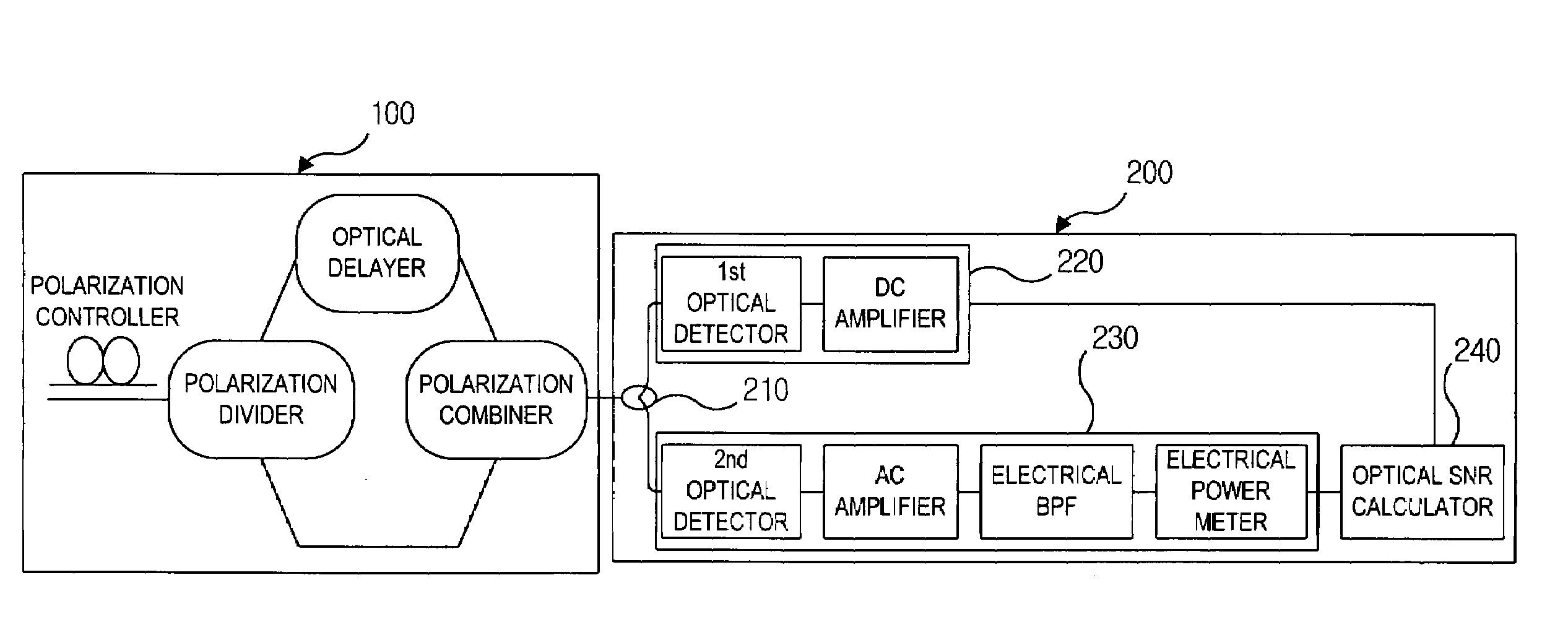
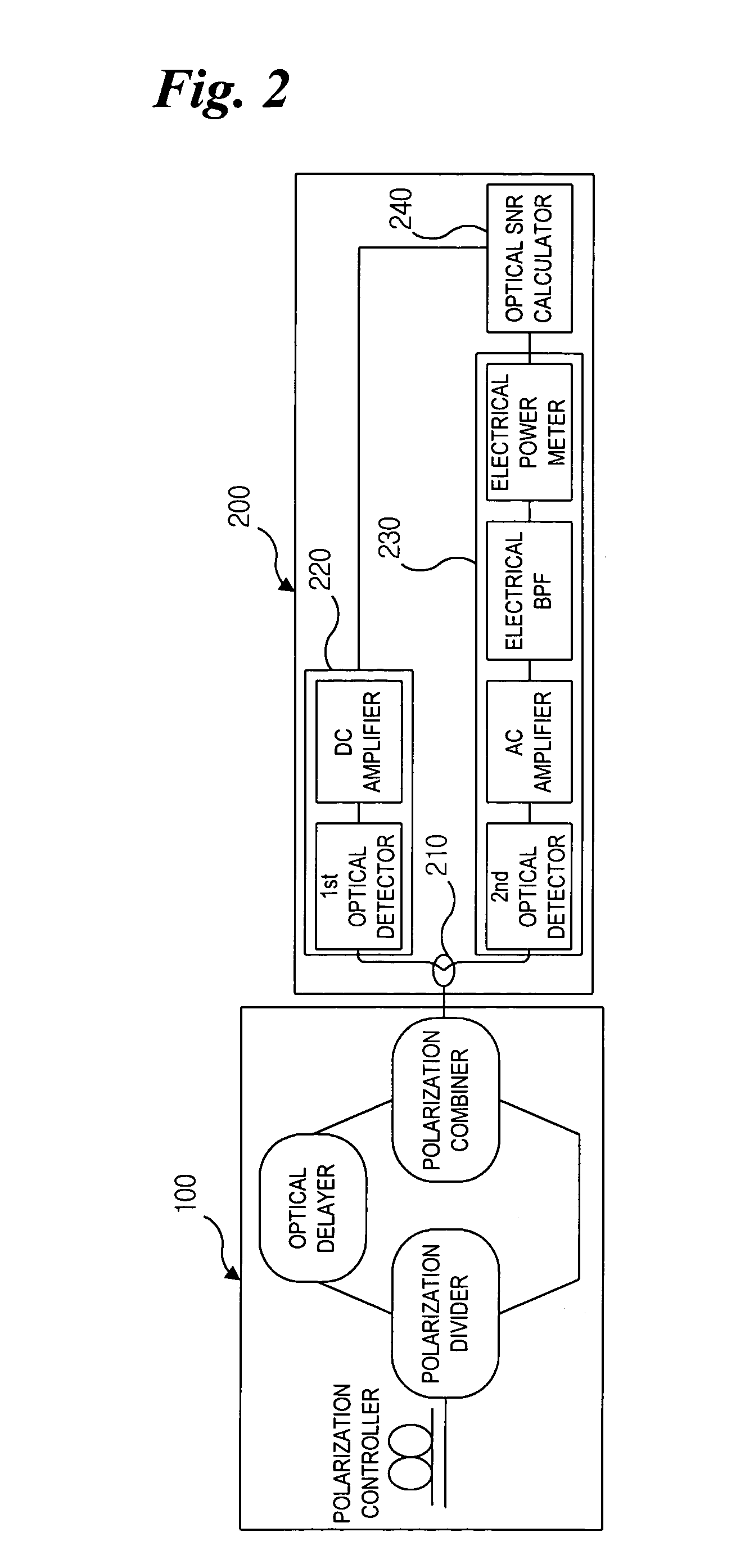
[0031]As shown in FIG. 2, the apparatus for monitoring the optical signal-to-noise ratio according to the first embodiment of the present invention includes an orthogonal polarization component module 100 and calculation means 200.

[0032]The orthogonal polarization component module 100 includes a polarization controller, a polarization divider, an optical delay element and a polarization combiner. The polarization controller receives an optical signal, and outputs it to the polarization divider while controlling first and second polarization components thereof perpendicular to each other to have the same intensity. The polarization divider receives the optical signal outputted from the polarization controller, and divides it into the first and second polarization components, and then outputs them. The optical delay element receives one of the first and second polarization components and delays and outputs the received one. The polarization combiner receives the two polarization compo...

embodiment 2

[0039]FIG. 3 illustrates the configuration of an apparatus for monitoring an optical signal-to-noise ratio according to a second embodiment of the present invention.

[0040]As shown in FIG. 3, the apparatus for monitoring the optical signal-to-noise ratio according to this embodiment includes an orthogonal polarization component module 100 and calculation means 300. The configuration and operation of the orthogonal polarization component module 100 in this embodiment is the same as that of the first embodiment, and a description thereof will thus be omitted in this embodiment.

[0041]The calculation means 300 includes an optical detector 310, an electrical intensity divider 320, average signal intensity measurement means 330, noise intensity measurement means 340 and an optical SNR calculator 350.

[0042]The optical detector 310 receives an optical signal outputted from the orthogonal polarization component module 100, and converts the received optical signal into an electrical signal and...


PUM


Abstract

Disclosed is an apparatus for monitoring an optical signal-to-noise ratio in a WDM optical network. The apparatus includes an orthogonal polarization component module for receiving an optical signal and outputting it after removing a signal component thereof at a specific frequency band; and calculation means for measuring both average signal and noise component intensity of the optical signal outputted from the orthogonal polarization component module. By removing a signal component at a specific frequency bandwidth and passing only a noise component through, it is possible to easily measure the noise intensity within a signal bandwidth that cannot be measured in general. A frequency band is set within a signal bandwidth, and the signal intensity is minimized at the set frequency band, so that it is possible to measure the optical signal-to-noise ratio even for a signal whose amplified spontaneous emission noise spectrum is not flat, irrespective of the signal pattern length.

Description

BACKGROUND OF THE INVENTION[0001]1. Field of the Invention[0002]The present invention relates to an apparatus for monitoring an optical signal-to-noise ratio, and more particularly to an apparatus for monitoring an optical signal-to-noise ratio in a WDM (Wavelength Division Multiplexing) optical network, using orthogonal polarization components of an optical signal.[0003]2. Description of the Related Art[0004]WDM technology is employed to transmit a number of independent optical channels, separated from each other, through a single optical fiber.[0005]Although it provides relatively low transmission rates, use of the WDM scheme enables a significant increase in the transmission capacity per optical fiber, which is thus effective in achieving a broadband high-speed communication network.[0006]In the WDM scheme, an optical amplifier for amplifying an optical signal is essential in compensating for loss in an optical fiber and increasing the transmission distance. However, the optical ...

Claims


Application Information

Patent Timeline
14 Aug 2007
Publication
US7257324B2
IPC
H04B10/08; H04B10/00
CPC
H04B10/077; H04B10/07955; H04B10/07; H04B10/2581
Inventors
CHUNG, YUN CHUR; YOUN, CHUN JU