Control device for free piston engine and method for the same

a control device and free piston technology, applied in the direction of free piston engines, machines/engines, mechanical equipment, etc., can solve the problems of difficult to make the pistons efficiently move back and forth, difficult to operate the conventional piston engine with constant efficiency, and mix gas may not be auto-ignited, etc., to achieve efficient operation of the free piston engine

Inactive Publication Date: 2007-08-21
DENSO CORP
View PDF4 Cites 47 Cited by
  • Summary
  • Abstract
  • Description
  • Claims
  • Application Information

AI Technical Summary

Benefits of technology

[0009]The present invention is made in view of the above problems. It is an object of the present invention to efficiently operate a free piston engine having two opposing pistons, in which mixed gas is auto-ignited by compression.
[0015]As above, according to the above control device, the displacements of the pistons are actively controlled so that the mixed gas in the combustion chamber is auto-ignited at a specified timing, which is the end of the compression stroke or close to the end, that is, at an optimum ignition timing for efficiently transforming an energy of a fuel to a driving force of the piston.
[0016]Therefore, it is possible to avoid such an inefficient combustion, in which the mixed gas is ignited before the optimum ignition timing or the mixed gas is not ignited even when the compression process ends and an expansion stroke starts, in which the pistons start moving away from each other. As a result, the energy of the fuel can be efficiently converted to the driving force of the pistons, to thereby constantly and efficiently operate the free piston engine.
[0018]In particular, when the temperature of the mixed gas and / or the air-fuel ratio is detected, the displacements of the pistons can be properly controlled based on the detected physical quantity(ies), so that the mixed gas can be auto-ignited at its optimum timing in each of the compression strokes. In other words, a failure of the auto-ignition or the auto-ignition at an improper timing can be prevented.
[0020]Accordingly, a more favorable effect can be obtained in the case that the pressure in the combustion chamber is detected in addition to the temperature and the air-fuel ratio of the mixed gas.
[0022]According to the above control device for the free piston engine, the kinetic energy of the first and second pistons produced by explosion of the mixed gas can be converted into the electric energy at the respective linear motors, so that the electric power can be obtained. As a result that the free piston engine can be efficiently operated, the electrical power can be likewise efficiently generated.

Problems solved by technology

In other cases, the mixed gas may not be auto-ignited even when the compression stroke has ended and the pistons start getting away from each other (that is, misfires of the free piston engine).
Therefore, it is difficult to operate the conventional piston engine with constant efficiency.
In other words, it is difficult to make the pistons efficiently move back-and-forth.
The inefficient operation of the free piston engine would result in the inefficient generation of the electric power using the free piston engine.

Method used


Image

  • Control device for free piston engine and method for the same
  • Control device for free piston engine and method for the same
  • Control device for free piston engine and method for the same

Examples


Embodiment Construction

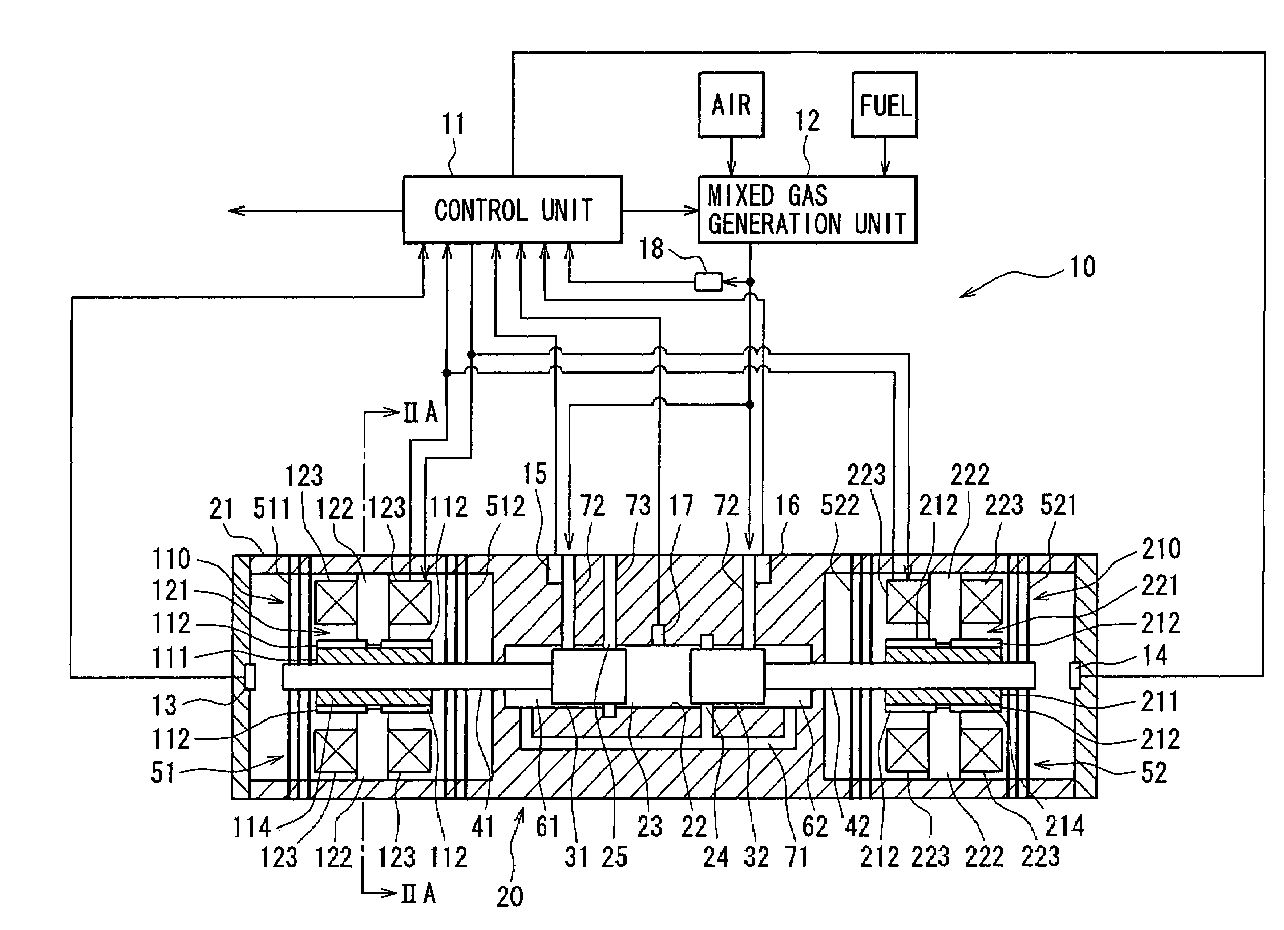
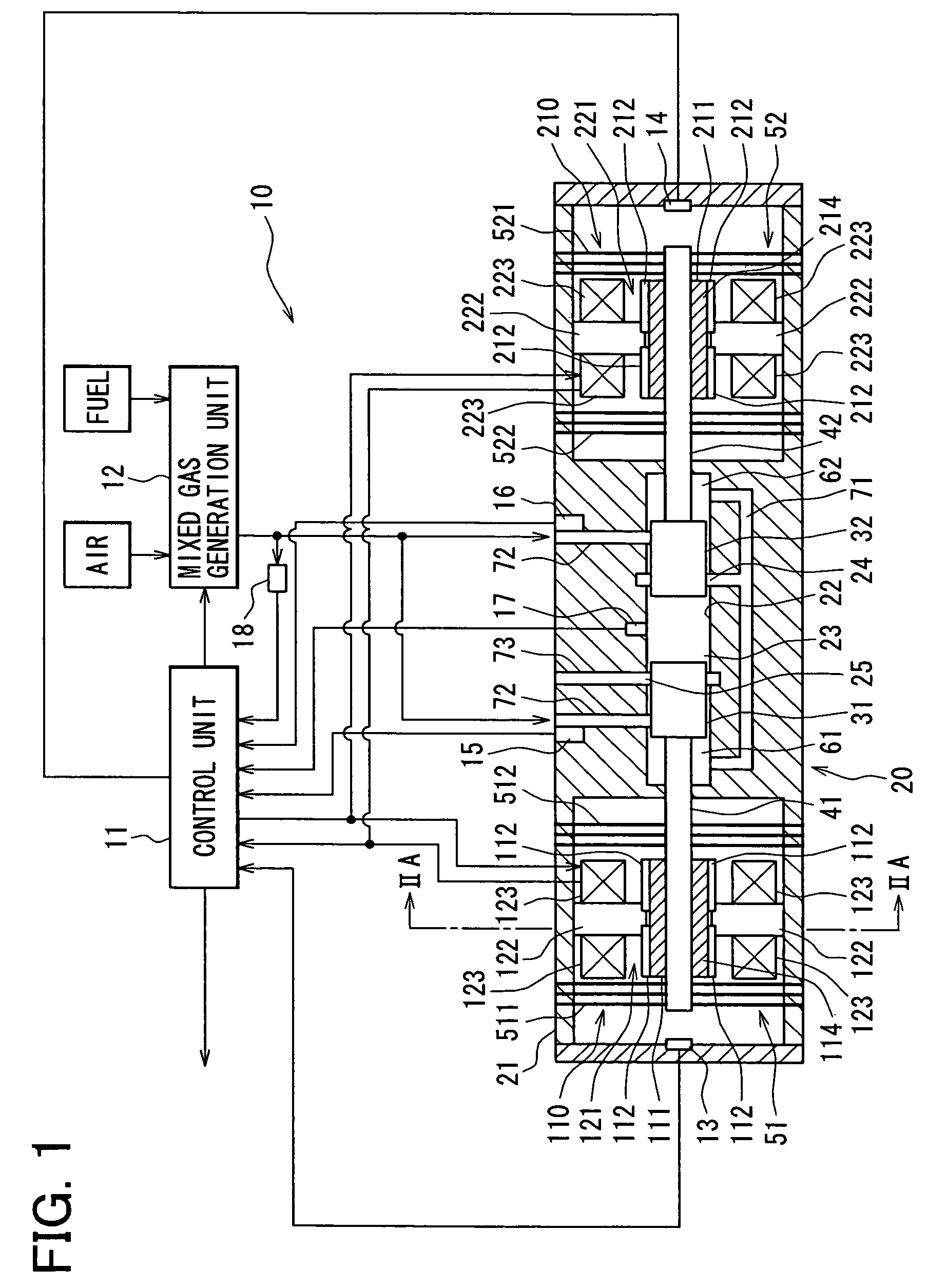
[0039]As shown in FIG. 1, an electric power generator 10 according to an embodiment of the present invention includes a free piston engine 20, a control unit 11, a mixed gas generation unit 12, a first linear motor 110, and a second linear motor 210. The control unit 11, which is mainly constructed by a microcomputer, controls the first and second linear motors 110 and 210 and the mixed gas generation unit 12 to operate the free piston engine 20 at an optimum state, so that electric power is generated at the linear motors 110 and 210.

[0040]The electric power generator 10 is connected with a motor or some other devices through, for example, an external battery (not shown). The power generator 10 is used as a power supply source for a small vehicle or a series-type hybrid vehicle.

[0041]The mixed gas generation unit 12 generates mixed gas of a predetermined air-fuel ratio from fuel and air. The control unit 11 controls the air-fuel ratio and an amount of the mixed gas to be supplied fr...


PUM


Abstract

A free piston engine has a pair of pistons opposing to each other and movable in a cylinder, to form a combustion chamber between the pistons. A mixed gas of air and fuel is supplied into the combustion chamber and the mixed gas is auto-ignited when it is compressed by the pistons. A temperature and / or an air-fuel ratio of the mixed gas, and / or a pressure in the combustion chamber is detected to control displacements of the pistons, so that the mixed gas is auto-ignited at an optimum timing to efficiently operate the free piston engine.

Description

CROSS REFERENCE TO RELATED APPLICATION[0001]This application is based on and incorporates herein by reference Japanese patent application No. 2004-363402 filed on Dec. 15, 2004.FIELD OF THE INVENTION[0002]The present invention relates to a control device and a method for controlling a free piston engine used for, for example, electric power generation.BACKGROUND OF THE INVENTION[0003]An electric power generator using a free piston engine is known, for example, in a PCT JP-Publication No. 2003-519328 (which corresponds to U.S. Pat. Nos. 6,397,793 and 6,276,313).[0004]The electric power generator disclosed in this publication has the free piston engine and a power generation means. The free piston engine includes two opposed pistons in a cylinder and back pressure chambers as air spring means respectively arranged at back sides of the pistons, and the power generation means has an electromagnet for transforming kinetic energy of the pistons into electric energy.[0005]In the free pisto...

Claims


Application Information

Patent Timeline
Patent Type & Authority Patents(United States)
IPC IPC(8): F02B71/00F02B71/04
CPCF02B63/04F02B71/04F02B63/041
Inventor NIIYAMA, YASUNORIKANEKO, TAKASHIHAGIWARA, YASUMASA
Owner DENSO CORP
Why Eureka
Try Eureka