Dialysis catheter

a catheter and dialysis technology, applied in the field of catheters, can solve the problems of complicated dissection, limited distance between the distal tip of the catheter and the cuff, and the neck is not the unobtrusive location of the catheter, and achieve the effect of easy access for removal

Inactive Publication Date: 2007-08-21
KERR ANDREW
View PDF17 Cites 28 Cited by
  • Summary
  • Abstract
  • Description
  • Claims
  • Application Information

AI Technical Summary

Benefits of technology

[0020]An alternate version of the catheter assembly may include may include a cuff tube with a proximal end, a distal end and a lumen extending between the ends. The lumen is configured so that the cuff tube can be telescoped over proximal portions of the catheter. The above described cuff may be mounted to an appropriate location on the outer periphery of the cuff tube. In this regard, the cuff tube can be formed with surface configurations on the outer periphery for positioning and holding the cuff. In other embodiments, the cuff may be premounted to a selected location on the cuff tube. The premounting of the cuff on the cuff tube can be achieved, for example, by adhesive. The cuff tube further may include a hub mounting structure at a location on the outer periphery near the proximal end. Additionally, the cuff tube may include means for constricting portions of the cuff tube into a secure mechanical and fluid tight engagement with the catheter. The hub of this embodiment is configured for secure mounting over proximal portions of the cuff tube. The mounting may be achieved by a snapped engagement of the hub mounting structure on the cuff tube with corresponding structure on the hub. The assembly of this embodiment is employed by initially positioning the catheter as described above. The cuff tube then is slid over proximal portions of the catheter and the attachments means near proximal portion of the cuff tube are tightened to achieve secure engagement of the cuff tube with the catheter. Portions of the catheter that extend proximally beyond the cuff tube then are trimmed. The hub then is mounted over and secured to the cuff tube. The hub can be configured to mount over or into proximal portions of the cuff tube. Additionally, engageable regions of cuff tube and the hub can be configured to compress the cuff tube or the hub inwardly to achieve a secure mechanical and fluid tight interconnection between the cuff tube, the catheter and the hub. This embodiment can avoid the need for a separate attachments means to secure the cuff tube to the catheter.
[0032]As noted above, a dialysis catheter is intentionally in communication with a high volume blood vessel. Accordingly, bleeding from the tunnel exit site remains a potential problem. However, the hub extension of the subject invention is configured to prevent bleeding from the tunnel exit site. Additionally, the hub extension provides an additional layer of protection for the catheter against ascending bacteria.

Problems solved by technology

However, the neck certainly is not the unobtrusive location for keeping the proximal end of the dialysis catheter between the periodic dialysis procedures.
This dissection can be complicated.
Accordingly, the doctor has limitations on the distance between the distal tip of the catheter and the cuff depending upon physical characteristics of the patient.
There are costs and complications associated with a need to maintain an inventory of different products.
The above-described Arrow Cannon catheter has the above-described problems associated with inventory management.
Additionally, the retrograde movement of the catheter through the tunnel requires a technique that many doctors are not accustomed to.
Furthermore, the intraoperative assembly of the compression sleeve with the compression cap requires more procedural steps and takes additional time.
However, the system shown in U.S. Pat. No. 5,989,213 is not trimmable and hence requires an extensive inventory of catheters of different length to ensure that an excess of the catheter is not disposed externally of the patient.

Method used


Image

  • Dialysis catheter
  • Dialysis catheter
  • Dialysis catheter

Examples


first embodiment

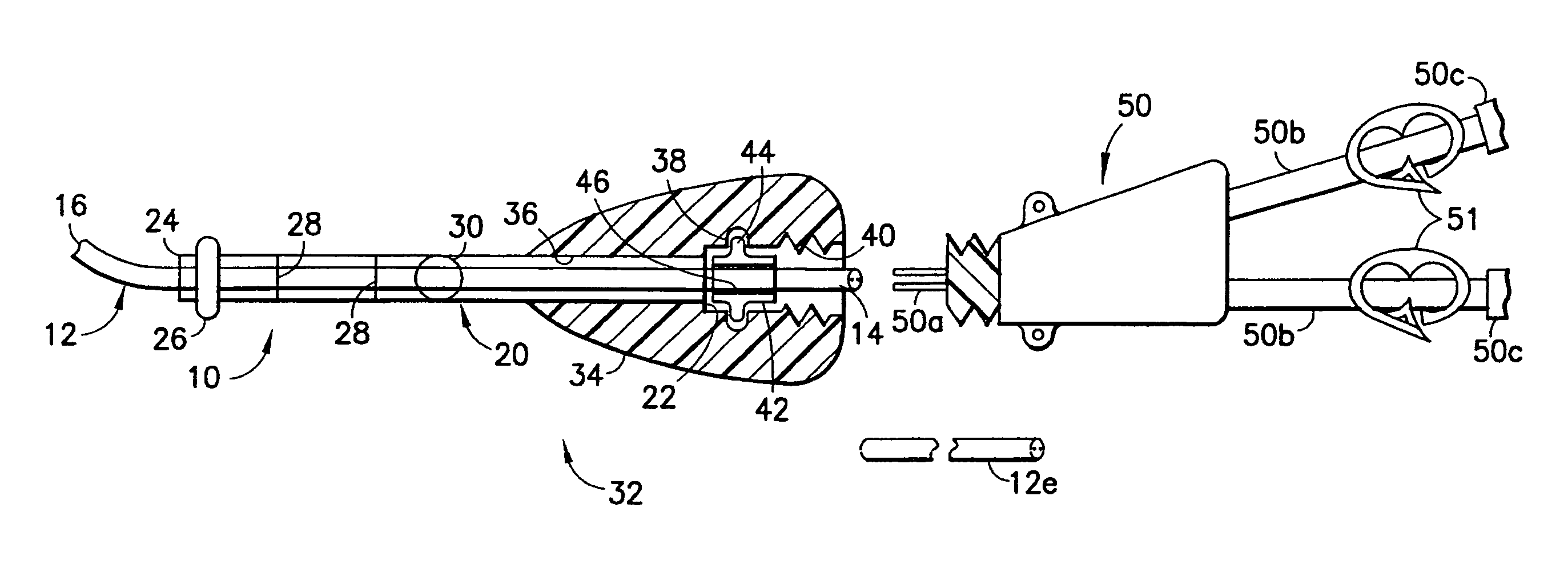
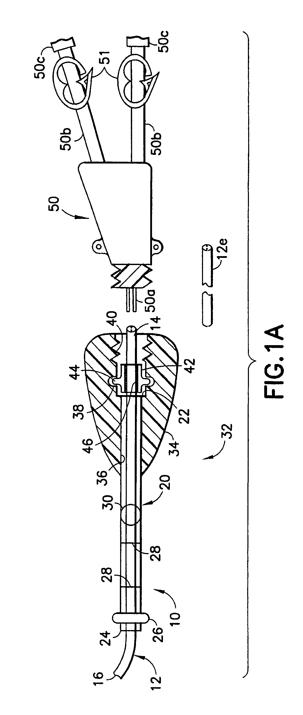
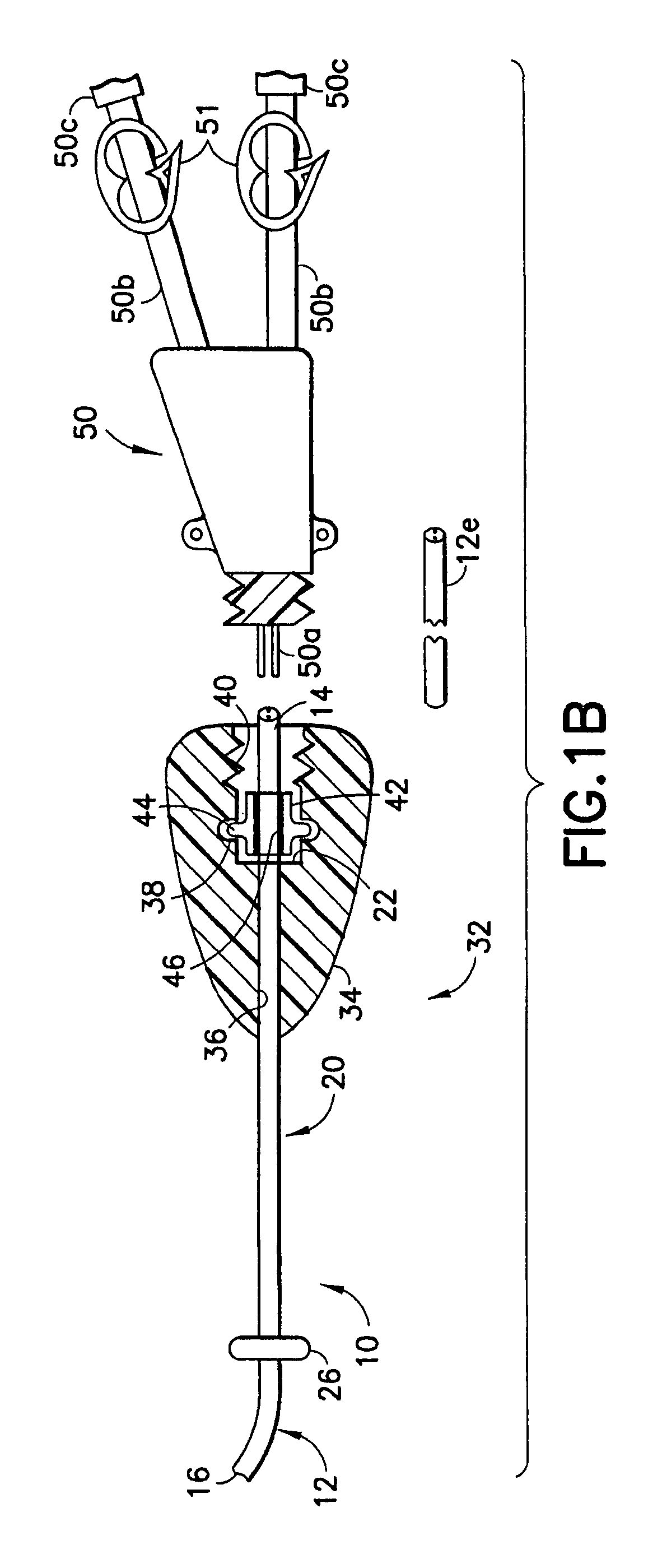
[0056]A dialysis catheter assembly in accordance with the invention is identified generally by the numeral 10 in FIG. 1A. The catheter assembly 10 includes a catheter 12 with a proximal end 14 and a distal end 16. The proximal end 14 will be disposed externally on the patient, while the distal end 16 will be positioned at a selected location in a blood vessel of the patient, and preferably in close proximity to the heart of the patient. A subcutaneous tube 20 is mounted over a portion of the catheter 12 near the proximal end 14. The subcutaneous tube 20 will be disposed in a subcutaneous tunnel extending from a location on the chest of the patient to a location near the neck of the patient. The tube 20 includes a proximal end 22 that will be disposed externally of the patient and a distal end 24 that will be in the subcutaneous tunnel. A polyester cuff 26 or other fibrosing agent is disposed near the distal end of the tube 24 and is configured to promote the growth of scar tissue th...

second embodiment

[0062]A catheter in accordance with the invention is identified by the numeral 62 in FIG. 7. The catheter 62 includes a proximal end 64 and a distal end 66. Portions of the catheter 62 adjacent the proximal end 64 are formed with non-cylindrical external surface configurations 68. In a preferred embodiment, as shown in FIG. 7, the exterior of the catheter 62 near the proximal end 64 includes an alternating arrangement of conical surfaces 68A intersecting radial surfaces 68B. Thus, a Christmas tree pattern is formed. The catheter 62 is used with a hub 70, as shown in FIG. 8. The hub 70 has a proximal end 72, a distal end 74 and a passage 76 extending therebetween. The passage 76 includes surface configurations that mate with the external surface configuration 68 near the proximal end 64 of the catheter 62. As a result, the proximal end 64 of the catheter 62 can be urged in a distal-to-proximal direction into the distal end 74 of the hub 70. This distal-to-proximal movement of the cat...

third embodiment

[0064]a hub in accordance with the subject invention is identified generally by the numeral 80 in FIG. 9. The hub 80 has a proximal end 82, a distal end 84 and a passage 86 extending therethrough. A notch 88 is formed on the outer surface of the hub 80 near the distal end 84. A cuff 90, as shown in FIG. 10, can be pressed over the distal end 84 of the hub 80 and forcibly retained in the notch 88 to compress the hub 80 into engagement with the catheter 12. This assembly can be used substantially as with the previous embodiments and ensures that the distal end 16 of the catheter 12 can be positioned precisely and that the cuff 90 can be disposed at the preferred position for anchoring in the tunnel.


PUM


Abstract

A catheter assembly includes catheter having proximal and distal ends and at least one lumen extending between the ends. At least one end of the catheter is formed from a material that can be trimmed to achieve a selected length for the catheter. A tubular connector is telescoped over the catheter and a hub is joined to the tubular connector. Proximal portions of the hub are configured for connection to a medical apparatus. A cuff is mounted around the tubular connector or the catheter. The cuff is formed from a material that will permit or promote the growth of scar tissue for anchoring the catheter device at least on a semi-permanent basis in a patient.

Description

[0001]This application claims priority on U.S. Provisional Patent Appl. No. 60 / 631,473, filed Nov. 29, 2004.BACKGROUND OF THE INVENTION[0002]1. Field of the Invention[0003]The invention relates to a catheter that can be used for dialysis or for other procedures where the catheter is implanted for an extended period of time.[0004]2. Description of the Related Art[0005]Dialysis and some chemotherapy regimens require a catheter to be implanted in a patient for an extended time (e.g., several weeks, several months or longer). Catheters for dialysis extend from an externally accessible location on the patient (typically on the chest) to a location where there is a high flow of blood (typically near the heart). The high blood flow enables a sufficient volume of blood to be processed through the catheter and cleaned by the dialysis machine. Catheters used for chemotherapy and other drug administration purposes are extended from an externally accessible location on the patient to a location...

Claims


Application Information

Patent Timeline
Patent Type & Authority Patents(United States)
IPC IPC(8): A61M25/16
CPCA61M25/0068A61M25/0097A61B17/32053A61M25/0014A61M39/1011A61M2025/0031A61M1/3653A61M1/3661
Inventor KERR, ANDREW
Owner KERR ANDREW
Why Eureka
Try Eureka