Apparatus and method for transmitting and receiving data using an antenna array in a mobile communication system

Active Publication Date: 2007-08-21
SAMSUNG ELECTRONICS CO LTD
View PDF28 Cites 166 Cited by
  • Summary
  • Abstract
  • Description
  • Claims
  • Application Information

AI Technical Summary

Benefits of technology

[0020]It is, therefore, a first object of the present invention to provide a data transmitting/receiving apparatus

Problems solved by technology

In general, a radio channel environment has low reliability relative wired channels due to multipath fading, shadowing, propagation attenuation, time-varying noise, and interference.
This is an obstacle to increasing data rate and thus many techniques have been proposed to overcome the limitations of the radio channels.
However, even an error control coded signal is not immune to burst errors in systematic bits or parity bits.
The burst errors often occur on a fading channel.
The error control coding and diversity techniques for radio channels, however, have limitations in satisfying the demands for high rate data service like Internet access and multimedia service unless frequency efficiency is increased.
Under a LOS (Line of Sight) environment, the antenna array system, which

Method used


Image

  • Apparatus and method for transmitting and receiving data using an antenna array in a mobile communication system
  • Apparatus and method for transmitting and receiving data using an antenna array in a mobile communication system
  • Apparatus and method for transmitting and receiving data using an antenna array in a mobile communication system

Examples


first embodiment

1. First Embodiment

[0076]In a first embodiment of the present invention, a transmitter determines a transmission status of each transmission antenna in a transmission antenna array and transmits data according to the transmission statuses. A receiver determines a reception status of each reception antenna in a reception antenna array and receives data according to the reception statuses.

[0077]For the above operations, the mobile communication system is configured and operated as follows.

[0078](1) The transmission status of each transmission antenna in the transmission antenna array is measured and control information corresponding to the transmission status is generated.

[0079](2) The transmission antennas are classified into data groups according to priority and the data groups are assigned to the transmission antennas according to the control information.

[0080](3) The status of each downlink channel is measured using a received signal and a signal received through each reception an...

second embodiment

2. Second Embodiment

[0109]In a second embodiment of the present invention, a Node B determines a transmission status of each transmission antenna in an antenna array and transmits the transmission status information to each MS, so that the transmission status information is under the same control in the Node B and the MS. The transmission statuses are determined in a same manner as in the first embodiment of the present invention.

[0110]FIG. 11 is a block diagram of a transmitter in a mobile communication system according to the second embodiment of the present invention. As illustrated in FIG. 11, the transmitter has a transmission status information transmitter 258 in addition to the components of the transmitter illustrated in FIG. 3. The transmission status information transmitter 258 transmits transmission status information about each transmission antenna received from a controller 246 to the UE through transmission antennas 250, 252, 254, and 256.

[0111]FIG. 12 is a block diagr...

third embodiment

3. Third Embodiment

[0112]In a third embodiment of the present invention, each UE determines the statuses of downlink channels received through reception antennas in an antenna array and feeds back the transmission status information to a BS, so that the transmission status information is under the same control in the Node B and the MS.

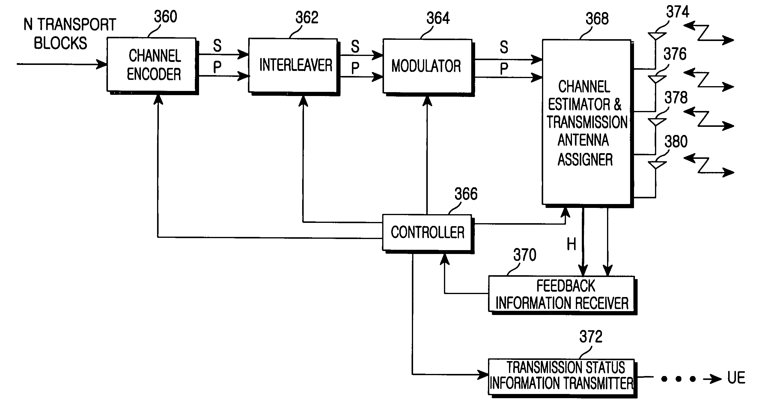
[0113]FIG. 13 is a block diagram of a transmitter in a mobile communication system according to the third embodiment of the present invention. Referring to FIG. 13, a channel estimator & transmission antenna assigner 308 receives feedback information H about the transmission statuses of transmission antennas 312, 314, 316, and 318 in a transmission antenna array from each UE. A feedback information receiver 310 feeds the transmission status information H to a controller 306. The controller 306 controls a transmission antenna assigner 308 to appropriately assign data groups to the transmission antennas 312, 314, 316, and 318 according to the transmissio...


PUM


Abstract

A data transmitting/receiving apparatus and method using an antenna array in a mobile communication system. A Node B measures a transmission status of each transmission antenna, classifies transmission data according to priority, and transmits to a UE high-priority data through a transmission antenna at a relatively good transmission status and low-priority data through a transmission antenna at a relatively poor transmission status.

Description

PRIORITY[0001]This application claims priority to an application entitled “Apparatus and Method for Transmitting and Receiving Data Using Antenna Array in a Mobile Communication System” filed in the Korean Industrial Property Office on Aug. 18, 2001 and assigned Serial No. 2001-49831, the contents of which are hereby incorporated by reference.BACKGROUND OF THE INVENTION[0002]1. Field of the Invention[0003]The present invention relates generally to a data transmitting / receiving apparatus and method in a mobile communication system including an antenna array, and in particular, to a data transmitting / receiving apparatus and method in a mobile communication system having an antenna array for antenna diversity.[0004]2. Description of the Related Art[0005]In general, a radio channel environment has low reliability relative wired channels due to multipath fading, shadowing, propagation attenuation, time-varying noise, and interference. This is an obstacle to increasing data rate and thus ...

Claims


Application Information

Patent Timeline
IPC IPC(8): H04B1/02H04B7/00H04J3/16H04B7/08H04B7/02H04B7/04H04B7/06H04B7/26H04L1/00H04W4/00H04W16/28H04W72/08
CPCH04B7/061H04L1/0041H04L1/0071H04L1/06H04W72/085H04B7/08H04L1/0003H04L1/0026H04W72/10H04L2001/0096H04L1/007H04W72/542H04W72/56H04B7/04H04B7/06H04B7/02
Inventor LEE, YONG-SUKKIM, SUNG-JINLEE, JONG-HYEUKPARK, SANG-HWANKIM, HUN-KEE
Owner SAMSUNG ELECTRONICS CO LTD
Why Eureka
Try Eureka