Oil cooling system of an air-cooled engine

a technology of oil cooling system and air-cooled engine, which is applied in the direction of lubricant mounting/connection, machines/engines, mechanical equipment, etc., can solve the problems of increasing the assembling time of the engine, complicated oil cooling system, and not improving the cooling performance, so as to improve the cooling performance and improve the cooling performance. , the effect of compact siz

Inactive Publication Date: 2007-08-28
SUBARU CORP
View PDF4 Cites 7 Cited by
  • Summary
  • Abstract
  • Description
  • Claims
  • Application Information

AI Technical Summary

Benefits of technology

[0008]In view of the above circumstances, the first object of the present invention is to provide the simple structure of the oil cooling system of the air-cooled engine, and to obtain a desirable cooling performance.
[0015]Furthermore, since the winds can directly blow the oil cooler without being disturbed by the oil filter, the cooling performance can be improved. Therefore, the oil cooling system with compact size and high performance can be achieved in a low cost.
[0016]Moreover, since the oil cooler comprises a pair of half bodies such as the base plate and the overlapping plate and the air-holes and the radiation fins are provided on the oil cooler to pass through the wind flows, the cooling performance of the oil cooler can be improved.

Problems solved by technology

However, in the case that the oil filter is directly assembled to the oil cooler, the oil filter prevents the wind from blowing the oil cooler, as a result the cooling performance is not improved.
For this reason, the oil cooling system will be complicated.
This causes not only increasing the assembling time of the engine but also increasing the production cost.

Method used


Image

  • Oil cooling system of an air-cooled engine
  • Oil cooling system of an air-cooled engine
  • Oil cooling system of an air-cooled engine

Examples


Embodiment Construction

[0026]A preferred embodiment of the present invention is explained with figures, however, the scope of the invention is not limited by the illustrated embodiments of the figures.

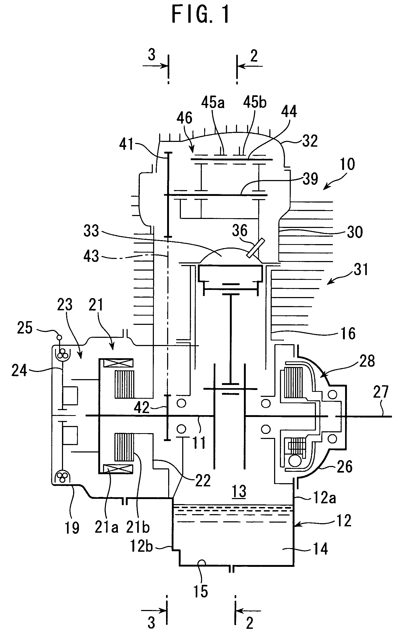
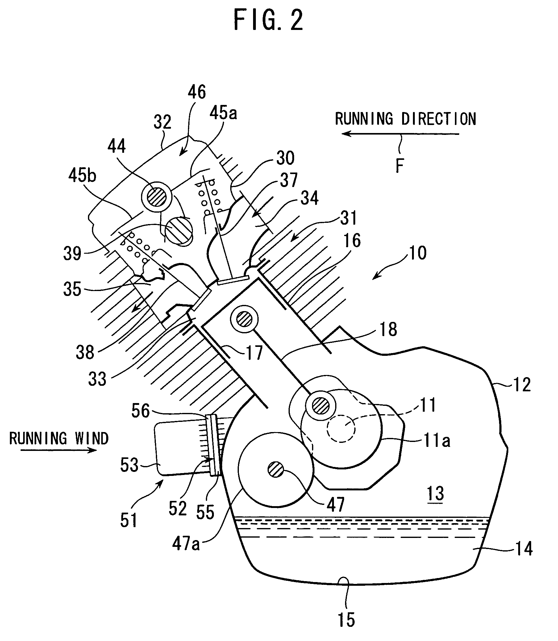
[0027]An engine 10 is used in a vehicle such as an all terrain vehicle (so-called as “ATV”). As shown in FIG. 1, the engine 10 comprises a crankcase 12, a cylinder 16, a cylinder head 30 assembled to the cylinder 16 and other component parts. The crankcase 12 rotatably incorporates a crankshaft 11 inside thereof. The crankcase 12 comprises a first half body 12a and a second half body 12b which is fixed to the first half body 12a. A crank room is formed inside the crankcase 12. The bottom of the crankcase 12 forms an oil pan 15 for reserving the engine oil. The cylinder 16 is assembled to the crankcase 12. A piston 17 is reciprocally incorporated in the cylinder 16. The piston 17 is connected to the crankshaft 11 through a connecting rod 18. Thus, the reciprocal motion of the piston 17 is converted to the rot...


PUM


Abstract

An oil cooling system of an air-cooled engine for cooling the oil reserved in a crankcase of the engine comprises a base plate assembled to the crankcase, an overlapping plate assembled to the base plate; an oil filter supported in the overlapping plate; and radiation fins formed on the base plate and the overlapping plate, wherein the base plate includes an inlet port for receiving the engine oil discharged from an oil pump of the engine, an outlet groove for outputting the engine oil and a first passage groove connecting the inlet port and the outlet groove, the overlapping plate includes an inlet groove opposed to the inlet port, an outlet port opposed to the outlet groove and a second passage groove opposed to the first passage groove to form an oil passage together with the first passage groove, and the base plate and the overlapping plate having through-holes where the filter outlet of the oil filter passes through for the connection with the crankcase.

Description

CROSS REFERENCE TO RELATED APPLICATIONS[0001]The disclosure of Japanese Application No. 2005-100519 filed on Mar. 31, 2005 including the specification, drawing and abstract is incorporated herein by reference in its entirety.FIELD OF THE INVENTION[0002]This invention is related to an oil cooling system for cooling the oil reserved in a crankcase of an engine, preferably the oil cooling system adapted to an air-cooled engine.BACKGROUND OF THE INVENTION[0003]Engine oil, which is supplied to the sliding portions that require lubrications, is stored in a crankcase of the engine. An air-cooled engine is used in an all-terrain vehicle (so-called as “ATV”). In the air-cooled engine, the engine is cooled by only the wind so that the temperature of the engine oil tends to rise.[0004]To solve this problem, Japanese Patent Laid-Open No. 2002-225574 discloses an air-cooled engine having an oil cooler assembled to the engine body so as to cool the engine oil.[0005]Furthermore, Japanese Patent La...

Claims


Application Information

Patent Timeline
Patent Type & Authority Patents(United States)
IPC IPC(8): F01M5/00
CPCF01M5/002F01M11/03F01M2011/033Y10S165/916
Inventor CHONAN, MITSUGIMATSUSHIMA, TOSHIYUKI
Owner SUBARU CORP
Why Eureka
Try Eureka