
Heating and cooling energy saving device

a technology of energy saving device and heating and cooling, which is applied in the direction of heating types, heating apparatus, instruments, etc., can solve the problems of inadequate supply, limited system, and all rooms are heated or cooled, and achieve substantial energy savings and reduce unnecessary heating or cooling

Inactive Publication Date: 2007-08-28
EOGA ANTHONY B
View PDF11 Cites 70 Cited by
  • Summary
  • Abstract
  • Description
  • Claims
  • Application Information

AI Technical Summary

Benefits of technology

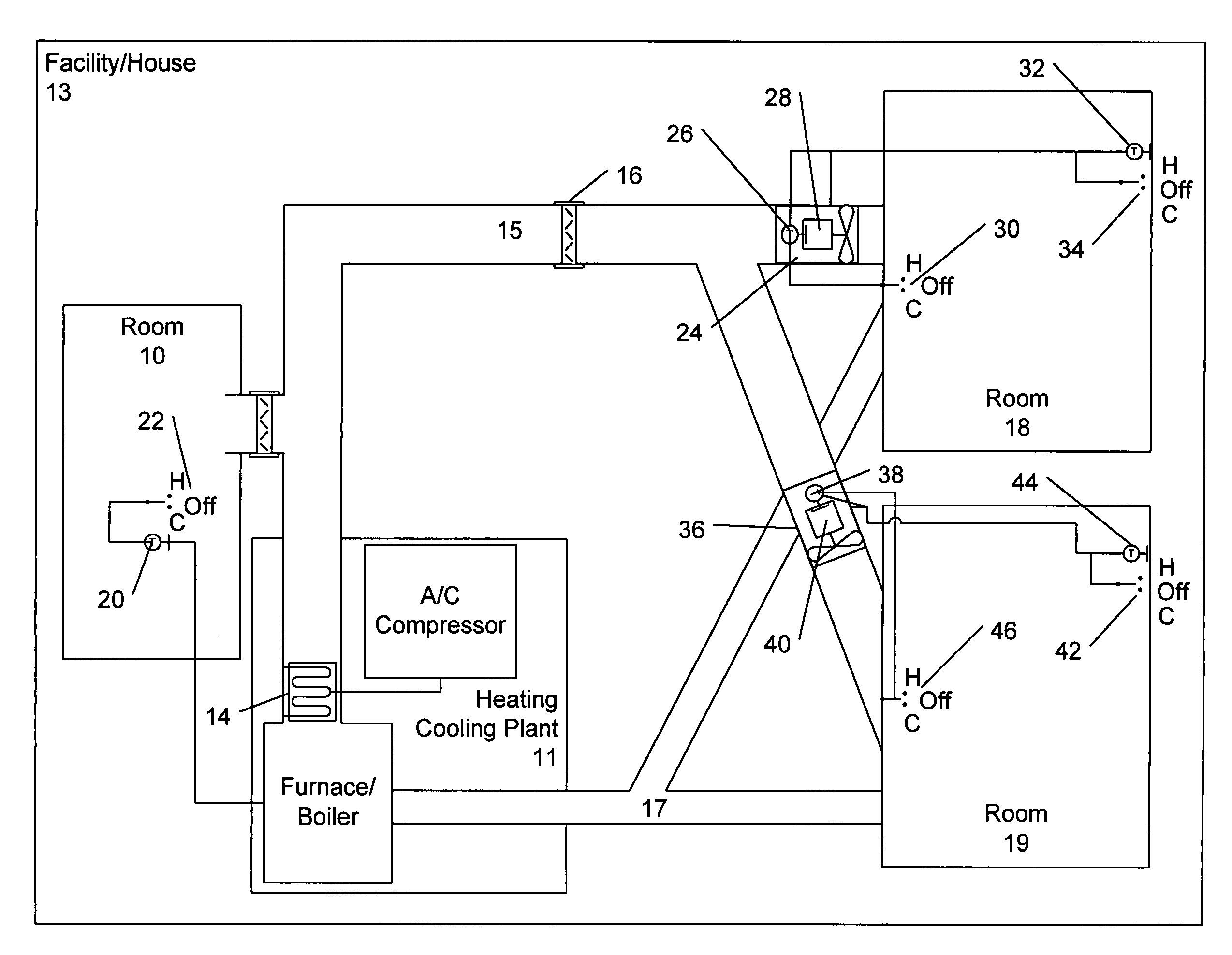
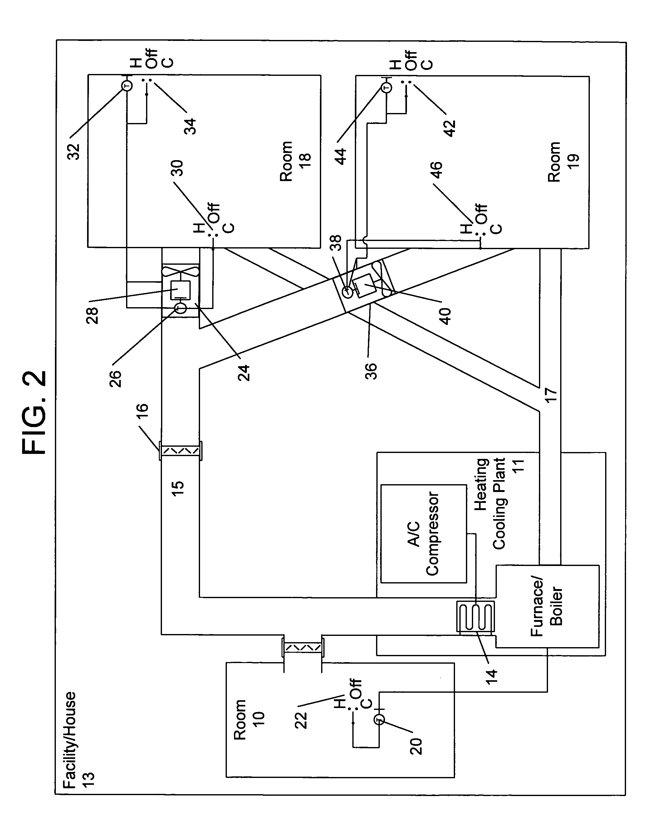
[0007]The present invention provides an area or room temperature control apparatus for a central heating and / or cooling systems having a central fluid heating or cooling plant or a central forced air heating or cooling plant with respective conduits which direct the heated or cooled fluid or air to the individual rooms being serviced by the same system in a home or an office complex. The area temperature control apparatus operates automatically to control the temperature in each individual room within a predetermined temperature range during any particular time period. It also operates to reduce unnecessary heating or cooling of individual rooms or areas consisting of one or more rooms during cyclical periods of use, whereby substantial energy savings may be realized with minimal compromise to comfort. More particularly, the area temperature control apparatus operates within heating / cooling systems to deliver heated or cooled air to individual rooms within a facility to maintain individual rooms substantially at a predetermined temperature after a first (main) thermostat controlling the heating / cooling plant is activated and the respective conduits attain a prescribed temperature.
[0008]The energy savings device (ESD) of the present invention provides for individual control of the temperature of each room within the facility. This device provides a fan and two additional thermostats to control the temperature in each room. One thermostat is located in the ESD to activate a fan only when the baseboard-heating element, cooling element, or conduit temperature provides a pre-selected sufficient temperature level range to activate a fan. The fan size is designed to provide sufficient air transfer capacity to increase or decrease the temperature of any room. The speed of the fan preferably provides airflow that exceeds the airflow velocity of the facility heating and cooling unit. The other thermostat is located remotely in each room and deactivates the fan when the temperature in any room exceeds or is less than the desired temperature level. Such a unit provides for increased comfort and energy savings from the reduced heating or cooling of rooms not in use, while reducing the environmental impact due to the efficiency of the unit.

Problems solved by technology

Such systems are limited in that they fail to adequately provide for the automatic, individual temperature control in each of the rooms or areas.
While more efficient than single zone systems, such systems are disadvantageous due to the prohibitively high costs of installing separate heating / cooling plants and conduits or pipes for each zone.
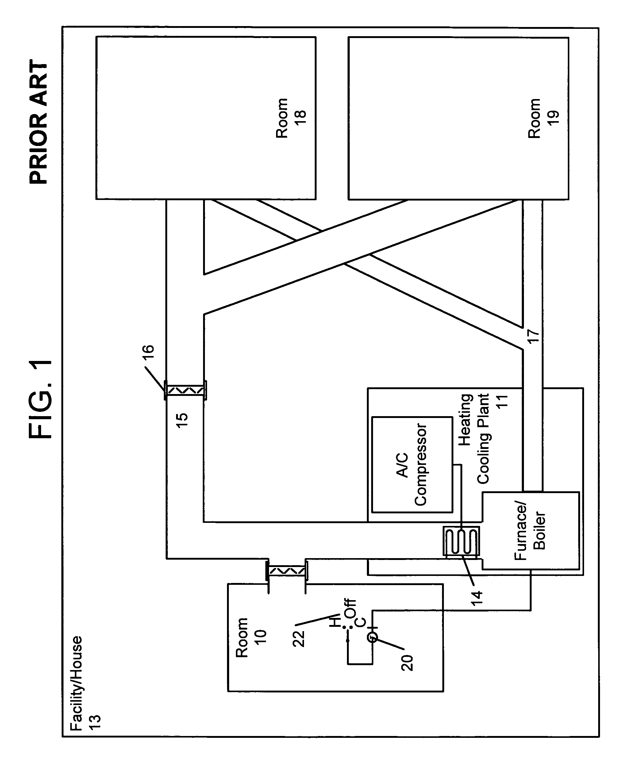
Another disadvantage of conventional single zone systems is that in homes that employ a single main thermostat 20 for all the rooms 10, 18 and 19, all of the rooms are heated or cooled to substantially the same temperature without any provision to control and maintain the individual room temperatures during the period of use or non-use.
This condition results in the wasting and excess use of energy.
Other systems, such as that described in U.S. Pat. No. 6,105,927 to Zelczer et al. disadvantageously require flow control devices that close the fluid flow.

Method used


Image

  • Heating and cooling energy saving device
  • Heating and cooling energy saving device
  • Heating and cooling energy saving device

Examples


Embodiment Construction

[0013]The present invention provides an area or room temperature control apparatus that operates within central heating and / or cooling systems having a central fluid heating or cooling plant or a central forced air heating or cooling plant with respective conduits which direct the heated or cooled fluid or air to the individual rooms being serviced in a home or an office complex. The area temperature control apparatus operates automatically to control the temperature in each individual room within a prescribed temperature range during any particular time period. It also operates to reduce unnecessary heating or cooling of individual rooms or areas consisting of one or more rooms during cyclical periods of use, whereby substantial energy saving may be realized with minimal compromise to comfort. More particularly, the area temperature control apparatus operates on the system to deliver heated or cooled air to individual rooms to substantially regulate the room temperature at a predet...


PUM


Abstract

A system for regulating the temperature of multiple areas within a facility using multiple energy savings devices (ESD) that each regulate the temperature of individual rooms or areas within a facility having a central heating and cooling plant. The device includes a fan and thermostats to control the temperature in each room. A first thermostat is located within the energy savings device to activate a fan only when a baseboard-heating element, cooling element or conduit provides a pre-selected sufficient temperature level range to activate a fan. Another thermostat is located remotely in each room and communicates to each ESD to deactivate the fan when the temperature in any room exceeds or is less than the desired temperature level. The desired temperature level may be higher or lower than a main thermostat setting that controls the central heating and cooling plant, in accordance with a heating or cooling mode, respectively.

Description

CROSS-REFERENCE TO RELATED APPLICATIONS[0001]This application is a continuation-in-part of, and claims the benefit of priority to, U.S. patent application Ser. No. 09 / 898,203, filed Jul. 3, 2001, now U.S. Pat. No. 6,688,384.FIELD OF THE INVENTION[0002]The present invention relates to heating and cooling systems. In particular, the present invention relates to an energy savings device used within conventional heating and cooling systems that regulates the temperature of predetermined areas of a facility and reduces the overall cost associated with heating and cooling the facility.BACKGROUND OF THE INVENTION[0003]FIG. 1 illustrates a conventional single zone (i.e., whole house) forced air heating and cooling system, which typically employs a single central heating and cooling plant 11 with respective conduits 15 and 17 to transfer the heated or cooled air to all the various areas or rooms 10, 18 and 19 serviced. In such systems, a single (main) control thermostat 20 and heating / coolin...

Claims


Application Information

Patent Timeline
IPC IPC(8): F24F11/00F24F11/04G05D23/19
CPCF24F11/0012G05D23/1919F24F2011/0067F24F11/30F24F2110/10F24F11/54F24F11/52F24F11/77F24F11/76F24F11/64F24F11/46
Inventor EOGA, ANTHONY B.
Owner EOGA ANTHONY B
Learn More