This helps you quickly interpret patents by identifying the three key elements:
Problems solved by technology
Method used
Benefits of technology
[0019]Providing the form in contact with the metal layers allows lami
Problems solved by technology
The use of stiffeners requires welding, complicates the manufacturing process and adds weight.
Stiffeners, their connection to the main plate or intersection with other main framing members are often the source of fatigue and corrosion problems.
Complex and congested structures that result from combining stiffened plates are often difficult to maintain and to provide adequate corrosion protection.
Such laminates generally employ foamed or
Method used
Image
Click on the blue label to locate the original text in one second.
Reading with bidirectional positioning of images and text.
Examples
Embodiment Construction
[0026]In the figures, like parts are identified by like numerals.
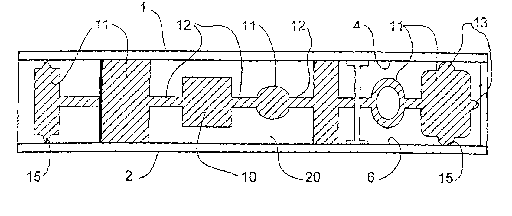
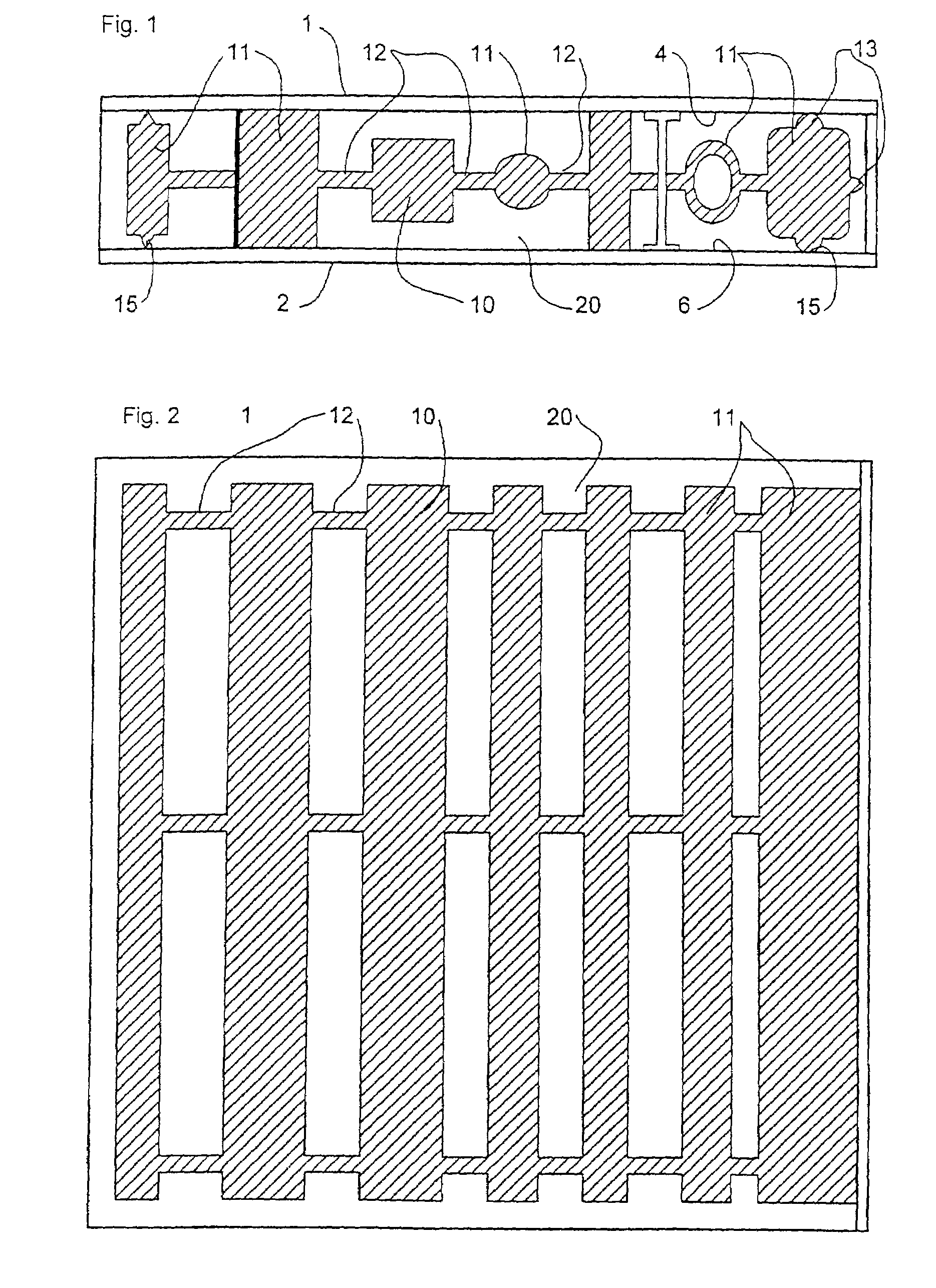
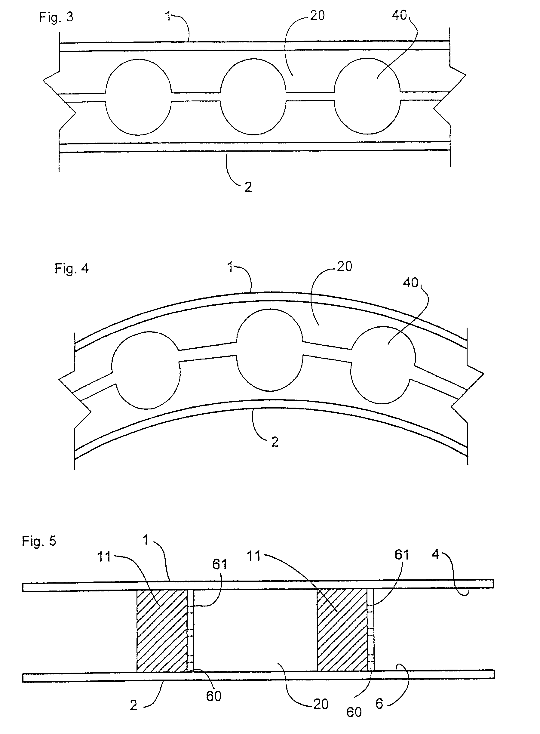
[0027]FIG. 1 is a cross-sectional view of a laminate member according to the present invention. The laminate member comprises a first outer layer 1, a form 10, an intermediate layer 20 and a second outer layer 2. The form 10 may be in part contact with the outer layers 1 and 2 at areas marked 15. The intermediate layer 20 is bonded to each of the first and second outer layers 1 and 2 with sufficient strength to transfer shear loads between the outer layers so as to form a composite structural member capable of bearing loads significantly greater than self-weight.
[0028]The precise load to be borne by the laminate member will depend on the application to which it is to be put. The ratio of volume of form 10 to volume of intermediate layer 20 is selected in accordance with the required physical properties. Such physical properties might include strength, stiffness or density.
[0029]The form 10 comprises several sub-section...
PUM
Property
Measurement
Unit
Length
aaaaa
aaaaa
Thickness
aaaaa
aaaaa
Pressure
aaaaa
aaaaa
Abstract
A composite structural laminate plate construction comprises two outer metal layers, a form between them and an elastomer layer bonded to the outer metal layers and filling the space between them other than that occupied by the form. The form may be foam and may be in partial contact with the metal layers.
Description
CROSS REFERENCE OF PRIOR APPLICATIONS[0001]This application is a Continuation of International Patent Application No. PCT / GB00 / 04198, filed Nov. 2, 2000, which was published under PCT Article 21(2) in English, the entire disclosure of which is hereby incorporated by reference. In addition, this application is also a Continuation-in-Part of pending U.S. patent application Ser. No. 09 / 496,072, filed Feb. 1, 2000, for COMPOSITE STEEL STRUCTURAL PLASTIC SANDWICH PLATE SYSTEMS, now U.S. Pat. No. 6,706,406, which is a Continuation-in-Part of U.S. patent application Ser. No. 09 / 053,551, filed on Apr. 1, 1998, for COMPOSITE STEEL STRUCTURAL PLASTIC SANDWICH PLATE SYSTEMS, now abandoned, which is a continuation of U.S. patent application Ser. No. 08 / 746,539, filed Nov. 13, 1996, for COMPOSITE STEEL STRUCTURAL PLATE SYSTEMS, now U.S. Pat. No. 5,778,813, the entire disclosure of which is hereby incorporated by reference.FIELD OF THE INVENTION[0002]The present invention relates to a composite s...
Claims
Application Information
Patent Timeline
Application Date:The date an application was filed.
Publication Date:The date a patent or application was officially published.
First Publication Date:The earliest publication date of a patent with the same application number.
Issue Date:Publication date of the patent grant document.
PCT Entry Date:The Entry date of PCT National Phase.
Estimated Expiry Date:The statutory expiry date of a patent right according to the Patent Law, and it is the longest term of protection that the patent right can achieve without the termination of the patent right due to other reasons(Term extension factor has been taken into account ).
Invalid Date:Actual expiry date is based on effective date or publication date of legal transaction data of invalid patent.