Light beam conditioner

Inactive Publication Date: 2007-08-28
WAFERMASTERS
View PDF3 Cites 10 Cited by
  • Summary
  • Abstract
  • Description
  • Claims
  • Application Information

AI Technical Summary

Benefits of technology

[0012]According to one embodiment of the present invention, a beam of collimated laser light originating from one or more lasers and / or from a source of continuous light spectra and prepared as a single co-linear beam containing a plurality of laser lines is incident on a beam splitter that is a part of a stack of beam splitters. The corresponding beam splitter breaks the incident beam into a number of beams equal to the number of beam splitters. The splitters are stacked in a serial manner, and preferably in serial physical contact, such that beam misalignments are minimized. The beams that are directed out of the stack each pass through a filter designed to pass only a narrow range of light centered about a selected wavelength, while blocking all others. Filters can be mechanically substituted to change the wavelength selected for transmission by using, for example, a filter wheel. Some beams so directed can also be blocked entirely so as to limit the number of wavelengths that are provided. A second stack of beam splitters in essentially mirrored configuration receives each of the individual beams, each of which now consists of a single wavelength, and the stack behaves in a reciprocal fashion, thus combining all the beams into a single beam which is directed from the beam conditioning system. A number of mirrors are placed strategically on back surfaces of certain beam splitters to improve the efficient provision of energy in each wavelength.

Problems solved by technology

However, some of the light interacts with the material at and near the surface and is scattered inelastically due to excitation of vibrational, rotational, and / or other low-frequency modes of the material.
One problem that arises in this connection is the means for selecting the preferred set of wavelengths, deleting or excluding others, and combining them into a single beam for optical characterization of material properties.
However, this is a highly inefficient system from the point of view of wasted beam energy, power consumption and duplication of costly laser hardware.
Furthermore, optical alignment to combine beams from a plurality of separate lasers or other light sources requires costly precision alignment.

Method used


Image

  • Light beam conditioner
  • Light beam conditioner
  • Light beam conditioner

Examples


Embodiment Construction

[0022]Systems and techniques provided herein may allow for more flexible spectroscopy than provided by existing spectroscopy systems.

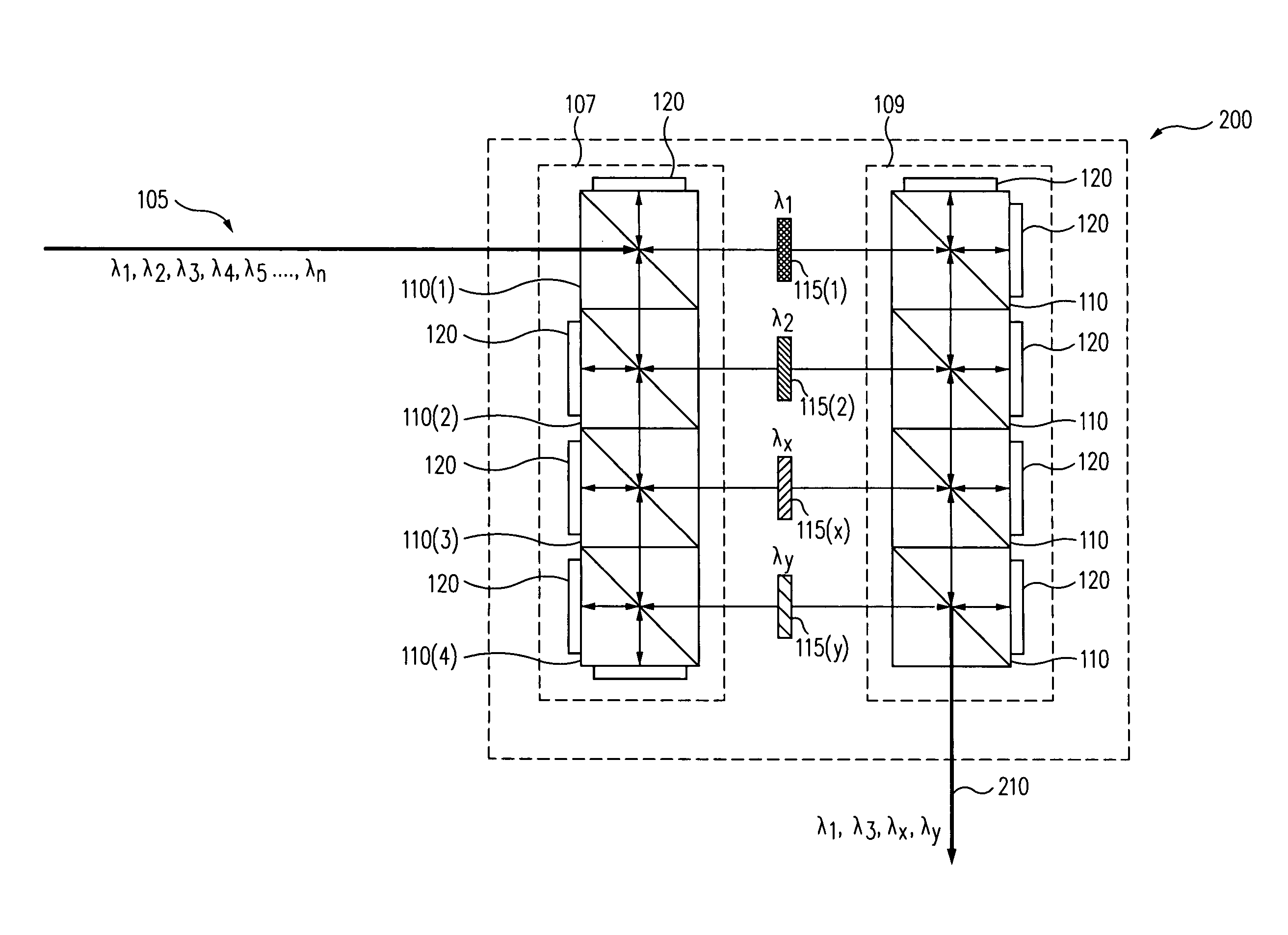
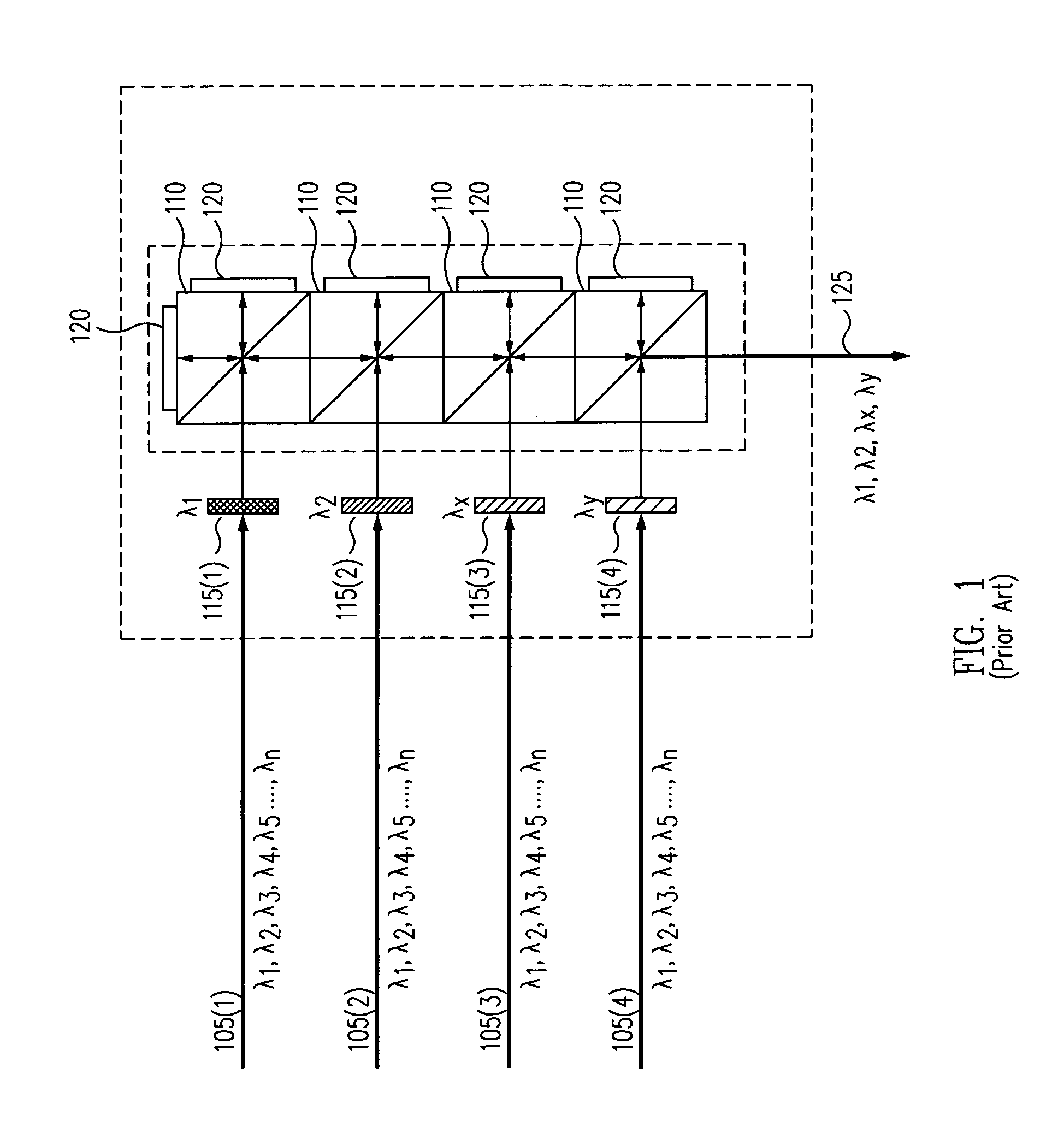
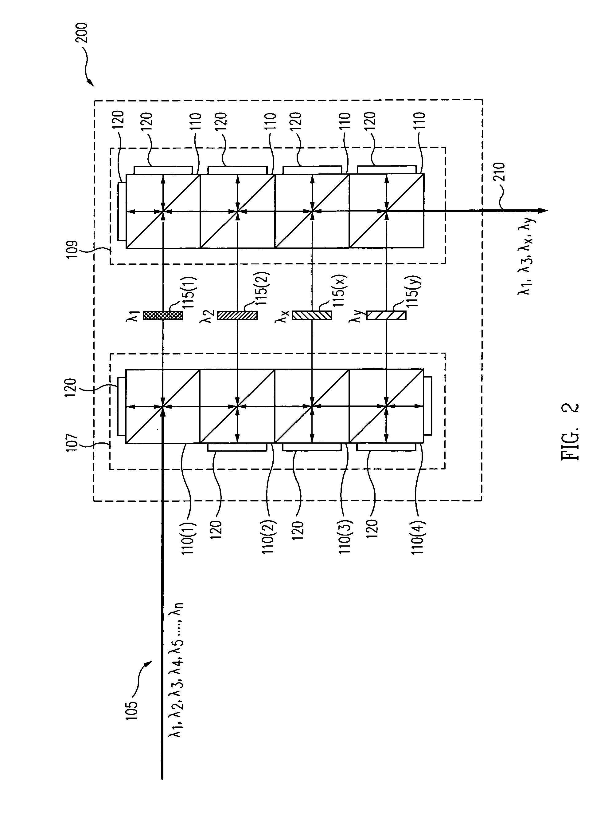
[0023]Optical spectroscopy systems often have need for selecting multiple wavelengths, either individually or simultaneously, in any desired combination. In Raman spectroscopy, for example, the argon ion laser is a popular choice, and generates a number of useful wavelengths (e.g., 457.9 nm, 488.0 nm, 514.5 nm, etc.). In certain materials, especially biological specimens, fluorescence is aggravated by illumination by shorter wavelength light, so that longer wavelength lasers, i.e., toward the infrared, are preferred. Therefore, a convenient means for selecting wavelengths from one or more laser sources is beneficial.

[0024]In order to provide enhanced flexibility in spectroscopy, systems and techniques provided herein include optical beam splitting or dispersal, filtering and recombining designs. As a result, a multiple wavelength source of light can be...


PUM


Abstract

A system and method for conditioning a beam of light comprised of several wavelengths by means of selecting from among the plurality of available wavelengths, a desired set of wavelengths simultaneously. A small number of multi-wavelength lasers or continuous spectra light sources, or both, may be the source for the plurality of light wavelengths, and a configuration of beam splitters / combiners, mirrors and wavelength selectable pass- and stop-filters provide a combined beam of light wavelengths selected from among the available wavelengths.

Description

BACKGROUND OF THE INVENTION[0001]1. Field of the Invention[0002]This invention generally relates to light beams and in particular to multi-wavelength lasers and continuous spectra light sources.[0003]2. Related Art[0004]A number of optical techniques may be used to obtain information about materials. One such technique is Raman spectroscopy. In Raman spectroscopy, laser light is incident on a surface of a material to be analyzed. Most of the light scatters elastically from the surface (which is referred to as Rayleigh scattering). However, some of the light interacts with the material at and near the surface and is scattered inelastically due to excitation of vibrational, rotational, and / or other low-frequency modes of the material. Detecting the frequencies of such vibrational states yields information about the molecular structure and quality of the material. The inelastically scattered light is shifted in wavelength with respect to the incident laser light, either down in frequen...

Claims


Application Information

Patent Timeline
IPC IPC(8): G02B27/14G02B27/10
CPCH01S3/005G01J3/44G01J3/10G01J2003/104G01J3/021G01J3/0227G01J3/0235G01J2003/1213G01J3/12G01J2003/1204G01J2003/1286G01J2003/1282G02B27/10
Inventor YOO, WOO SIKKANG, KITAEK
Owner WAFERMASTERS
Why Eureka
Try Eureka