Control method

Active Publication Date: 2007-08-28
ROBERT BOSCH GMBH
View PDF15 Cites 5 Cited by
  • Summary
  • Abstract
  • Description
  • Claims
  • Application Information

AI Technical Summary

Benefits of technology

[0003]An exemplary method according to the present invention may provide that information which is specific to the wireless transmission protocol, i.e., the protocol for communication between communication partners of the wireless portion of the LAN, may be transmitted via the core network. The exemplary method according to the present invention may be used for the transmission of control information which is specific to the wireless transmission protocol, since this may allow individual procedures to be performed at a considerably higher speed in the wireless portion of the LAN. In addition, the wireless interface may be relieved of data, so that the overall performance of the network may be enhanced. Furthermore, some services may become feasible for the first time due to the use of control information which may be specific to the wireless transmission protocol, in particular, service and maintenance services, which may not be available if no wireless-transmission-specific control information is transmittable via the core network.
[0005]A handover at the at least one terminal from communication with the first wireless station to communication with the second wireless station may be supported by an appropriate selection of the time interval so that the at least one link may not be interrupted. Therefore, continuous communication may be ensured between a terminal and a wireless station, even in the event of a handover from one wireless station to another wireless station at the terminal.
[0009]The control messages may be encrypted prior to being transmitted. This may provide greater security against unauthorized eavesdropping or corruption of the exchanged control messages.

Problems solved by technology

In contrast with TCP (Transmission Control Protocol), in this case no functions may be provided for data security; therefore, there may be no security against duplication or loss, or against individual data packets overtaking one another on the IP network.
The communication protocol of the core network, i.e., the IP protocol, for example, may be used in the entire LAN; however, it may not be configured for specific signaling between the communication partners of the wireless portion of the LAN.

Method used


Image

  • Control method
  • Control method
  • Control method

Examples


Embodiment Construction

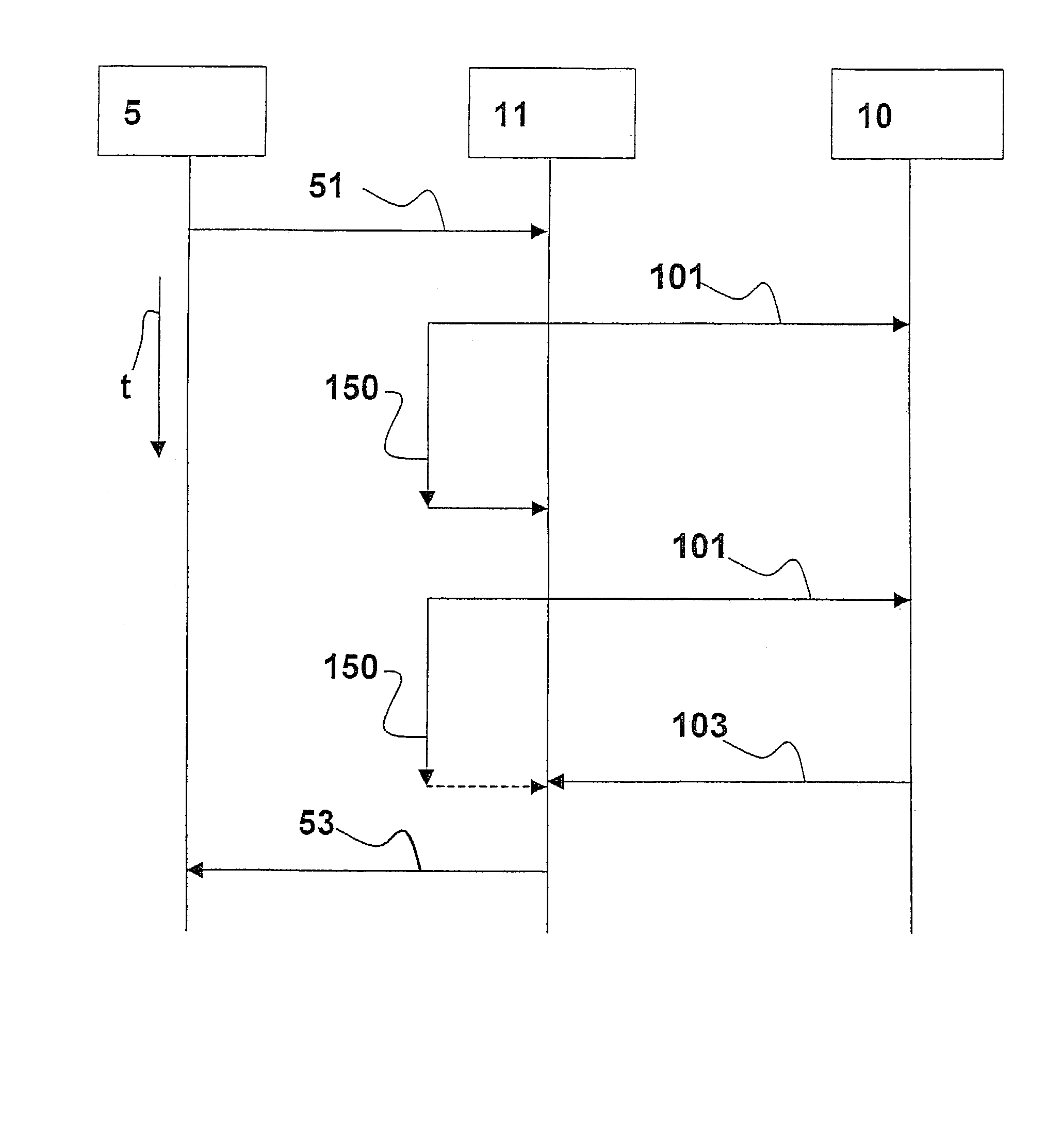
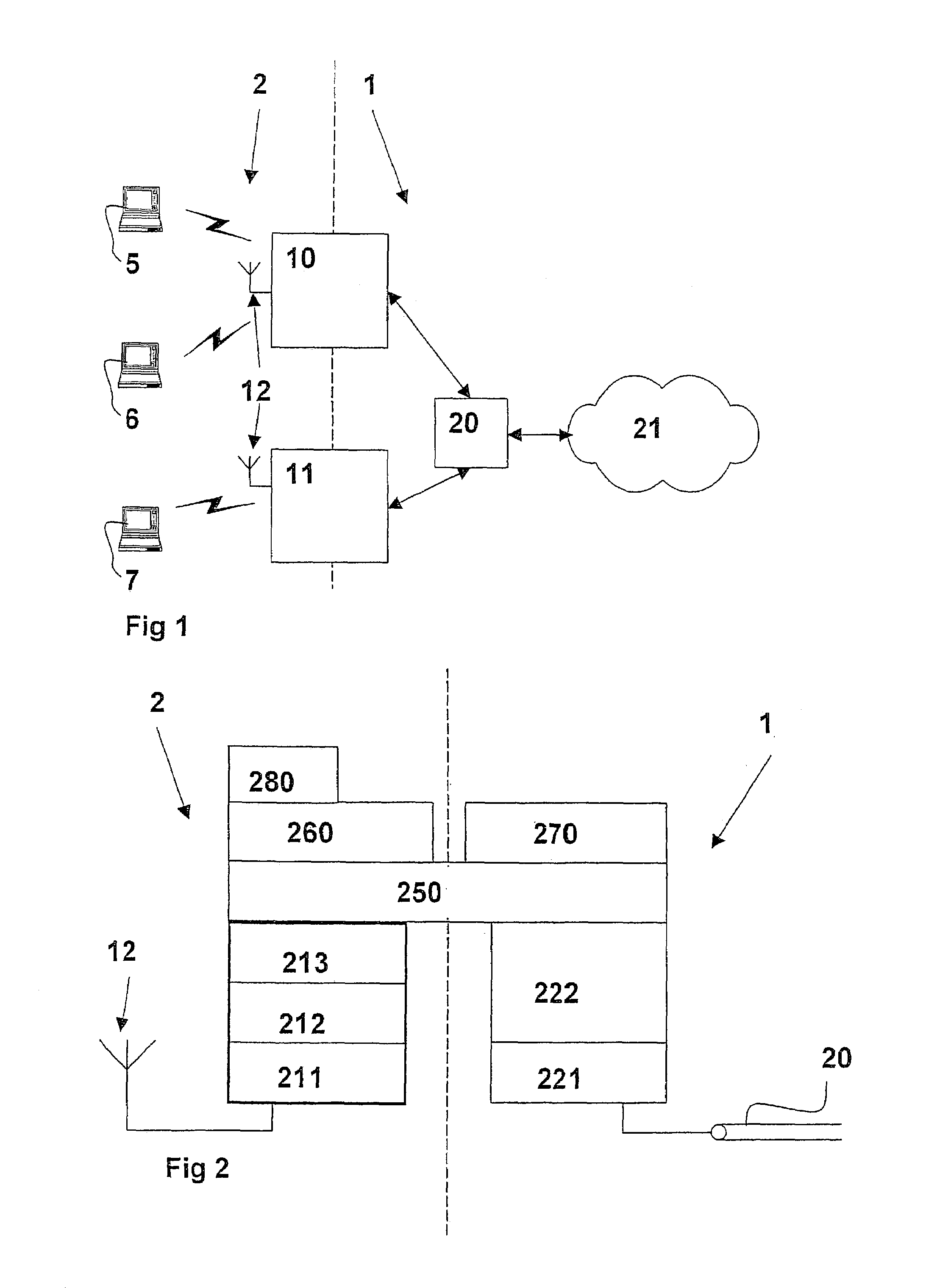
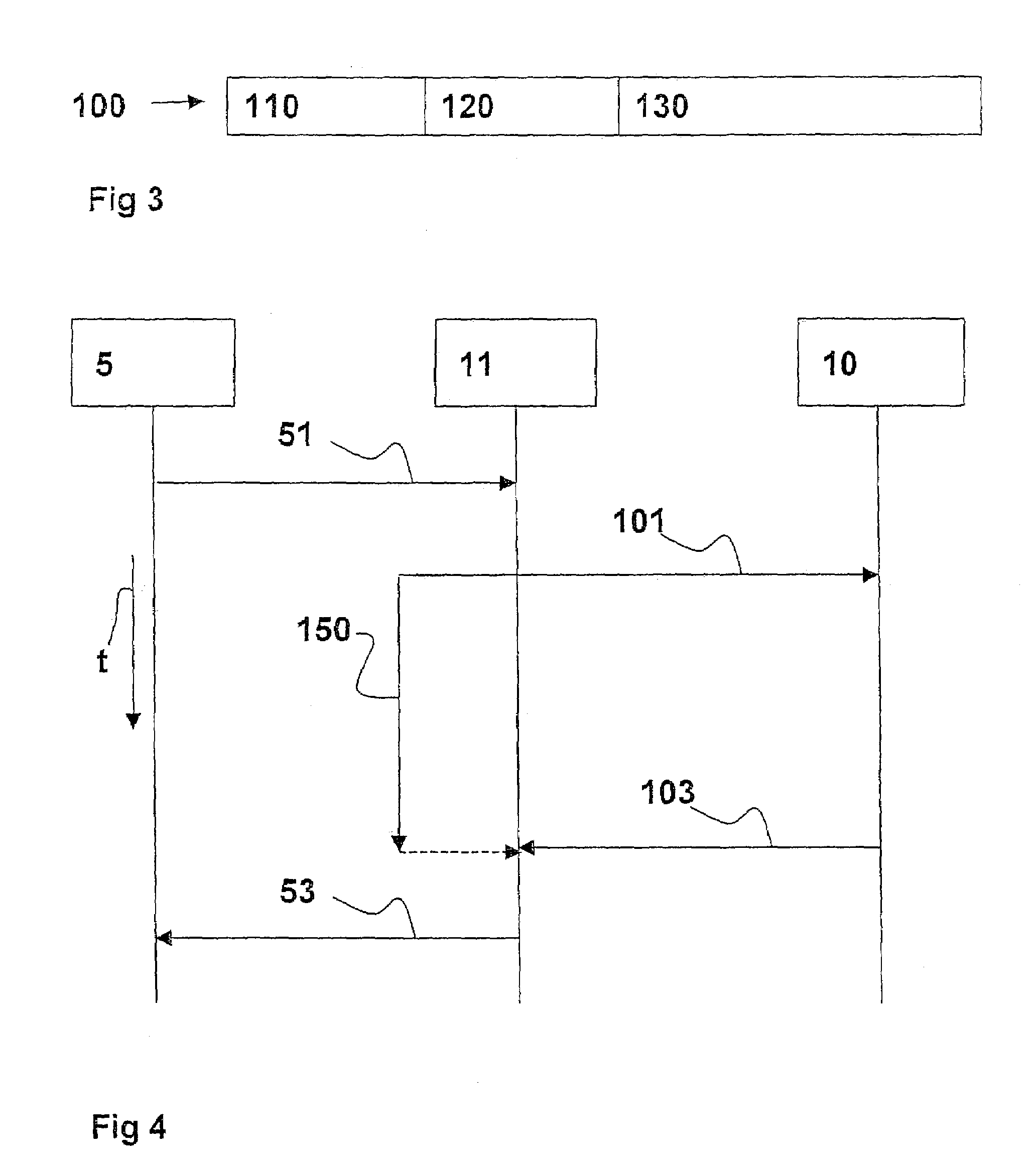
[0017]FIG. 1 shows a wireless LAN which has a core network 1 and a wireless portion 2 of the LAN. Core network 1 has a first wireless station 10, a second wireless station 11, a communication link 20, and additional stations 21 of core network 1. Both first wireless station 10 and second wireless station 11 are connected bidirectionally to communication link 20. Furthermore, communication link 20 is connected bidirectionally to additional stations 21 of core network 1. Wireless stations 10, 11 are also parts of the wireless portion of the LAN. For this purpose, first wireless station 10 and second wireless station 11 each include a transmitting / receiving antenna 12. A first terminal 5, a second terminal 6, and a third terminal 7 are also parts of wireless portion 2 of the LAN. Terminals 5, 6, and 7 are equipped with transmitting / receiving antennas (not shown) and thus are capable of engaging in wireless communication with wireless stations 10, 11. A broken line separates wireless po...


PUM


Abstract

A method of controlling a first wireless station and a second wireless station is described, the wireless stations being connected with one another via at least one communication link and being controlled according to a communication protocol, the first wireless station communicating with at least one terminal according to a frame-structured wireless transmission protocol using packet transfer, with control messages being defined via an additional protocol layer using the communication protocol for controlling the at least one link and / or for managing the wireless stations.

Description

FIELD OF THE INVENTION[0001]The present invention relates to a method of controlling wireless stations in a wireless network.BACKGROUND INFORMATION[0002]Wireless networks in the form of LANs (Local Area Networks) may be implemented using an at least partially wireless LAN. Such a wireless LAN may be implemented, for example, as a cellular network, in which a central unit or a wireless station serves a wireless cell. A plurality of terminals may be located in this wireless cell. The wireless stations may be connected via a wire-bound network such as an IP network, for example. One example of such a wireless LAN may include the “Type 2 BRAN / HIPERLAN” standardization project of ETSI (European Telecommunication Standards Institute). Thus, a wireless LAN may contain a core network, which may be wire-bound, via which the wireless stations are connected to one another. The wireless stations may communicate with one another via the core network according to a common communication protocol s...

Claims


Application Information

Patent Timeline
IPC IPC(8): H04B17/00G06F11/00H04J1/16H04L12/26H04L12/28H04L12/56H04L29/06H04L29/08
CPCH04L29/06H04W76/04H04L69/32H04W76/20H04L9/40H04L69/321
Inventor VOLLMER, VASCO
Owner ROBERT BOSCH GMBH
Why Eureka
Try Eureka