Unloaded lift offset rotor system for a helicopter

a technology of offset rotors and helicopters, which is applied in the direction of liquid fuel engines, vessel construction, marine propulsion, etc., can solve the problems of limiting the forward speed of the helicopter, limiting both the maximum speed of the helicopter and its efficiency in forward flight, and the practical implementation of such a technology did not realize the desired increase in efficiency. , to achieve the effect of improving the functionality and performance of the helicopter, reducing the drag on the non-rotating portion

Inactive Publication Date: 2007-09-04
THE BOEING CO
View PDF4 Cites 69 Cited by
  • Summary
  • Abstract
  • Description
  • Claims
  • Application Information

AI Technical Summary

Benefits of technology

[0011]Moreover, another advantage of the present invention is at least one fairing to reduce drag on non-rotating portions of a rotor system.
[0012]The present invention improves functionality and performance of a helicopter and / or a tandem rotor aircraft.

Problems solved by technology

There is an inherent tendency for the retreating blade of a helicopter to stall in forward flight, which limits the forward speed of the helicopter.
However flapping, while eliminating steady rolling moments on the airframe, also limits both the maximum speed of the helicopter, as well as its efficiency in forward flight.
Although the coaxial rigid rotor design was successful in demonstrating the concept of avoiding retreating blade stall, the practical implementation thereof did not realize the increase in efficiency as desired.
This lack of performance is a result of the loads and high vibratory moments that are generated by the design.
These moments often result in undesired airframe and rotor stresses.
In addition, the choice of a coaxial rotor system introduces a second rotor hub that, for a light helicopter, increases the parasite drag of the aircraft by nearly 30% over a single main rotor equivalent helicopter.
This increase in parasite drag negatively affects or cancels some of the efficiencies gained through the lift offset operation.

Method used


Image

  • Unloaded lift offset rotor system for a helicopter
  • Unloaded lift offset rotor system for a helicopter
  • Unloaded lift offset rotor system for a helicopter

Examples


Embodiment Construction

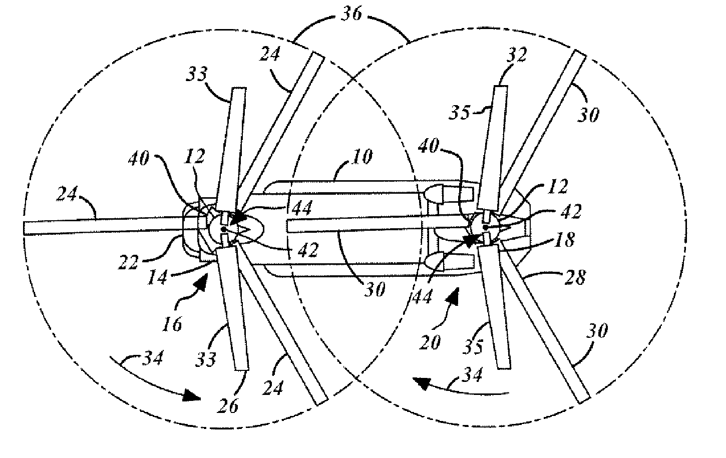
[0023]In each of the following figures, the same reference numerals are used to refer to the same components. While the present invention is described with respect to a tandem rotor helicopter system having reduced loading, vibration, and drag characteristics, the present invention may be adapted for various applications and systems known in the art. The present invention is applicable to various helicopter configurations including single main rotor, tandem, side-by-side, tri-rotor, and quad rotor configurations, as well as compound configurations using auxiliary propulsion.

[0024]The application of lift offset operation to a tandem rotor helicopter is not straightforward. For example, in using a coaxial rigid rotor design, since the rotors are required to be rigid, the design does not provide the ability to tilt the tip-path-plane of each rotor independent of the helicopter attitude. The capability to tilt the tip-path-plane of each rotor independently is the primary means of contro...


PUM


Abstract

A rotor system (12) for a helicopter (10) includes a rotating shaft (82). A gimbaled hub assembly (56) is coupled to the rotating shaft (82). Rotating blades (24) and non-rotating blades (33) are coupled to the gimbaled hub assembly (56). The non-rotating blades (33) provide lift for the helicopter (10) in forward flight unloading the rotating blades. The rotating and non-rotating blades (24, 33) provide equal and opposite rolling moments for lift offset operation.

Description

TECHNICAL FIELD[0001]The present invention relates generally to lift offset rotor systems for a helicopter. More particularly, the present invention relates to a system for providing lift offset with reduced loads and vibration for increased vehicle speed.BACKGROUND OF THE INVENTION[0002]There is an inherent tendency for the retreating blade of a helicopter to stall in forward flight, which limits the forward speed of the helicopter. As helicopter rotors fly in forward flight, there is an asymmetry in lift between the advancing and retreating sides of the rotor that transmit a rolling moment to the helicopter when rigidly connected. Conventional helicopter rotors eliminate the rolling moment through the introduction of flap hinges or a gimbaled mechanism at the root of the rotor blades. The asymmetry in lift causes the blades to flap (“flapping”) which then equalizes the lift on the advancing and retreating sides. However flapping, while eliminating steady rolling moments on the air...

Claims


Application Information

Patent Timeline
Patent Type & Authority Patents(United States)
IPC IPC(8): B64C27/00
CPCB64C27/08B64C27/26B64C27/59
Inventor ZIENTEK, THOMAS A.
Owner THE BOEING CO
Why Eureka
Try Eureka