Method and device for measuring the rotational speed of a pulse-activated electric motor based on a frequency of current ripples

a technology of pulse-activated electric motors and measurement methods, which is applied in the direction of motor/generator/converter stoppers, electronic commutators, dynamo-electric converter control, etc., can solve the problem that the level of voltage is not a very precise measure of speed, the method is not suitable for precise regulation, and the device tends to have a high cos

Inactive Publication Date: 2007-09-04
ROBERT BOSCH GMBH
View PDF17 Cites 10 Cited by
  • Summary
  • Abstract
  • Description
  • Claims
  • Application Information

AI Technical Summary

Benefits of technology

[0007]In contrast, the method according to the present invention and the device according to the present invention offer the advantage that it is possible for the speed of an electric motor activated in a pulsed fashion to be detected simply and cost-effectively, but also precisely.

Problems solved by technology

However, such devices tend to have a high cost.
However, the level of the voltage is not a very precise measure of the speed, so this method is not suitable for precise regulation.
In addition, this solution is not suitable for motors activated in a pulsed fashion.
However, the measurement is made more difficult by the constant change between the activated and non-activated phases of the motor.
The shorter the current pulses, which depends on the selected pulse frequency, the target speed, and the load on the motor, the less certain the measuring signal becomes, which can result in erroneous control and thus to fluctuations in the speed.

Method used


Image

  • Method and device for measuring the rotational speed of a pulse-activated electric motor based on a frequency of current ripples
  • Method and device for measuring the rotational speed of a pulse-activated electric motor based on a frequency of current ripples
  • Method and device for measuring the rotational speed of a pulse-activated electric motor based on a frequency of current ripples

Examples


Embodiment Construction

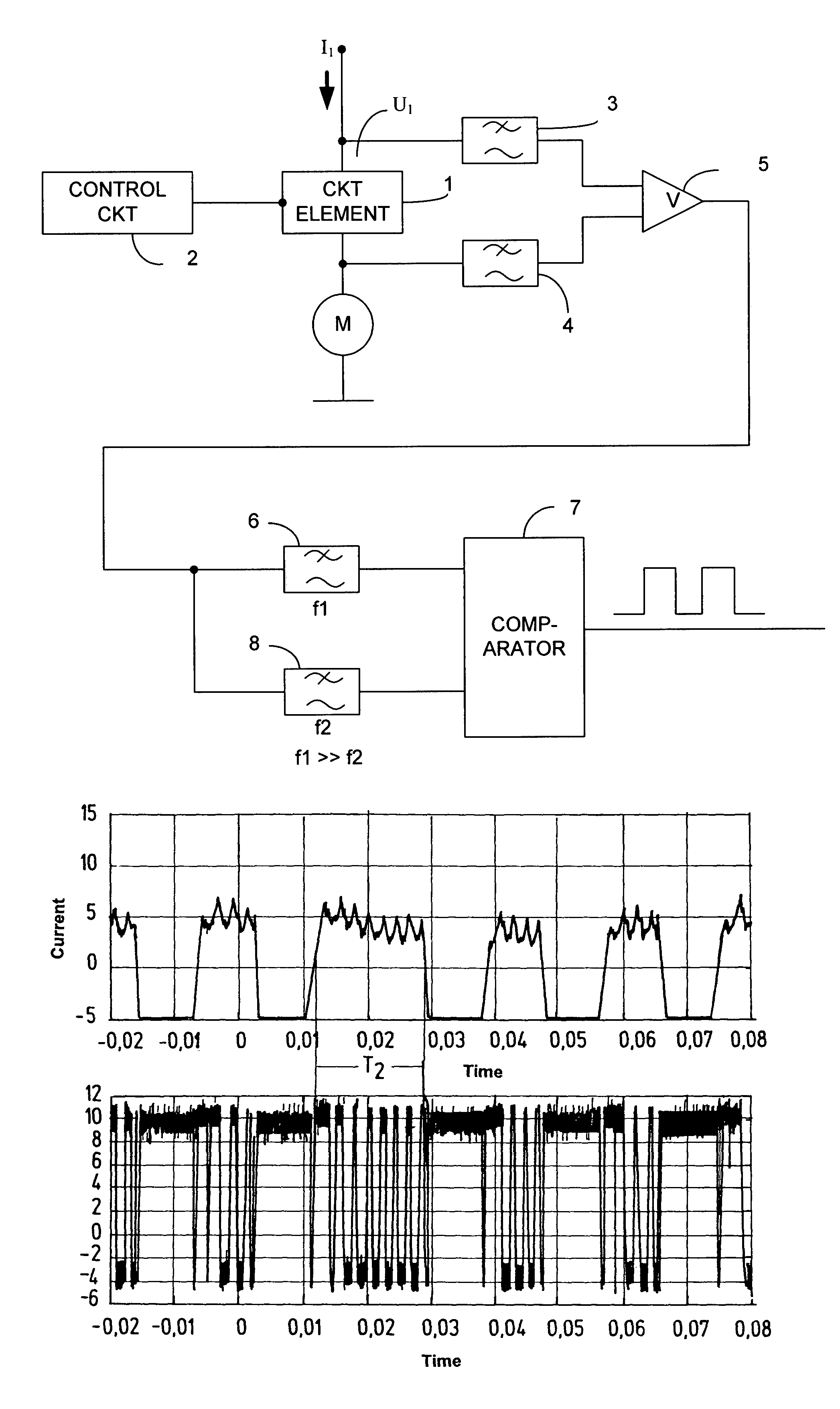
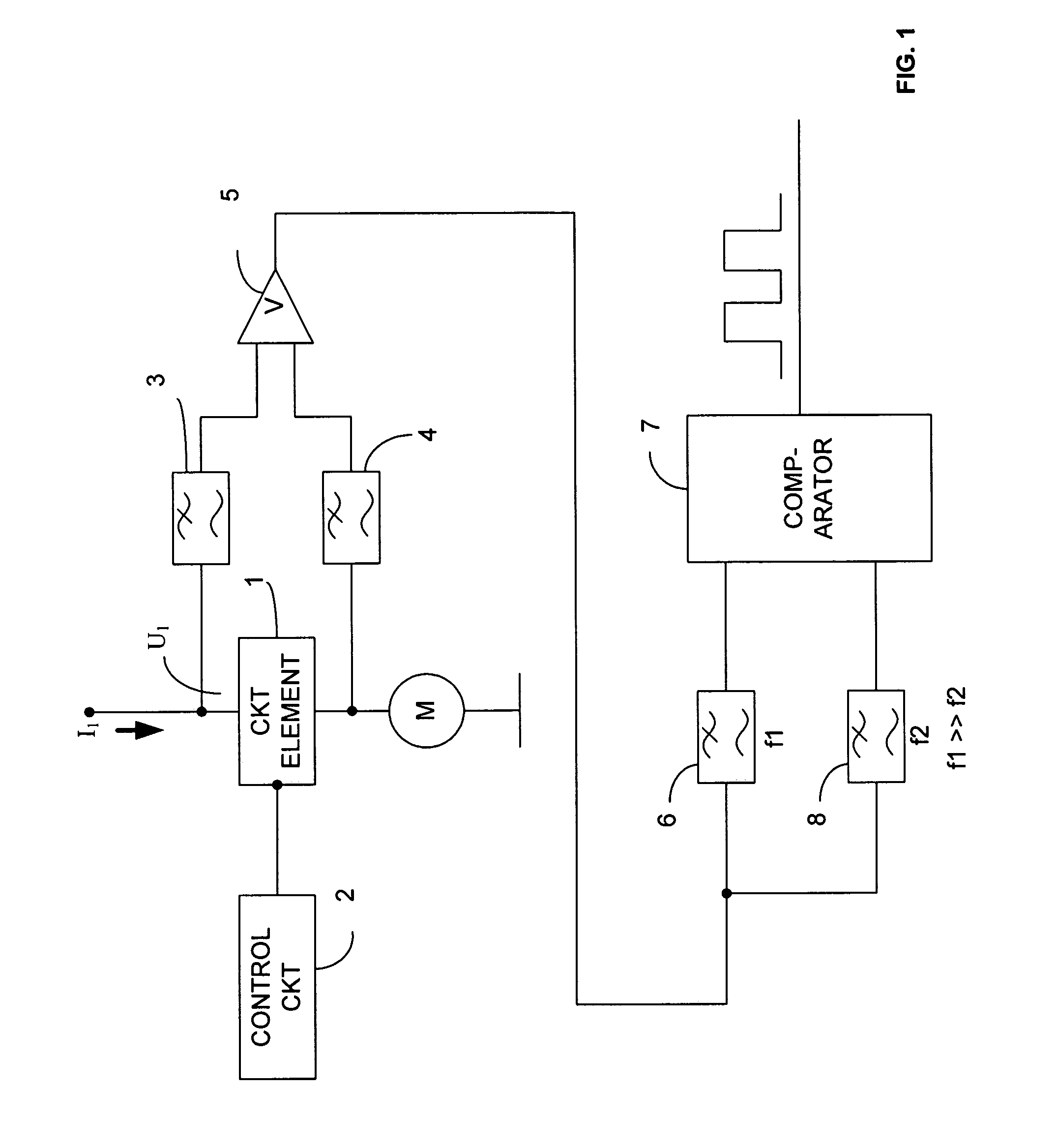
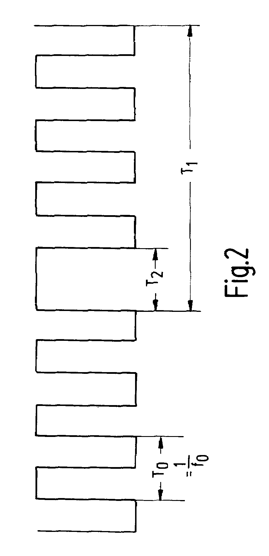
[0017]FIG. 1 shows a basic circuit diagram of the arrangement, for example, for a pump drive in a motor vehicle. A motor M is controlled by a control circuit 2 using PWM by way of a circuit element 1, for example, a transistor. A correspondingly lower speed n than in the case of constant activation of motor M is generated from the on / off switching ratio. Because of the vehicle wiring system, pulsing frequency f0 must be at least 50 Hz, for example. During the activation phase, higher-frequency oscillations whose frequency is proportional to speed n of motor M are caused in motor current Imotor (current ripple) by the commutation of the current at the collector of the motor. The duration of an individual current ripple depends on the number of the pole pairs and rotational speed n of motor M.

[0018]According to the method of the present invention, motor M is fully activated for a certain time period, or measuring time T2 (see FIG. 2) after the expiration of a time interval T1, for exa...


PUM


Abstract

A method and a device for measuring the speed of a pulse-activated electric motor are described. According to this method, the motor is fully activated at time intervals to be determined for a defined measuring time by the circuit element provided for timing and, in this time, the frequency of the current ripples, which is proportional to the motor speed, is measured. A current-proportional voltage measuring device is located on the circuit element, on whose load side are located an amplifier, filters, and an evaluation circuit in the form of a comparator for determining the frequency of the current ripples flowing in a measured phase during which the motor is fully activated.

Description

FIELD OF THE INVENTION[0001]The present invention relates to a method and a device for measuring the rotational speed of an electric motor activated in a pulsed fashion.BACKGROUND INFORMATION[0002]In order to determine the rotational speed of an electric motor for the purpose of speed regulation, magnetic or optical transmitters are known that are attached to the shaft of the motor and that are read by magnetic and / or optical sensors on the stator housing. However, such devices tend to have a high cost.[0003]For electric motors that are operated using pulse width modulation (PWM) voltage supply, i.e., in a pulsed fashion, a simpler and more cost-effective method is known to measure the voltage produced by the generator in the non-activated phases, the level of said voltage being proportional to the rotational speed of the motor.[0004]However, the level of the voltage is not a very precise measure of the speed, so this method is not suitable for precise regulation.[0005]German Publis...

Claims


Application Information

Patent Timeline
Patent Type & Authority Patents(United States)
IPC IPC(8): G01P3/46G01P3/44G01P3/48H02P6/18
CPCG01P3/44G01P3/48H02P7/00H02P7/0094
Inventor MICKE, MARCSIEVERT, HOLGERHACHTEL, JUERGENHERTLEIN, GUENTHER
Owner ROBERT BOSCH GMBH
Why Eureka
Try Eureka